 thereprocase
A closer look at the airflow.
A new transient CFD study puts finer cells around the duct edges and laptop lips. The mesh is built. Initial solver diagnostics show that further mesh and runtime work is required before quantitative results.
The standard mesh check passes, but three expanded checks fail. Sustained vortex shedding and settled lip suction have not been established.
The mesh around the lips
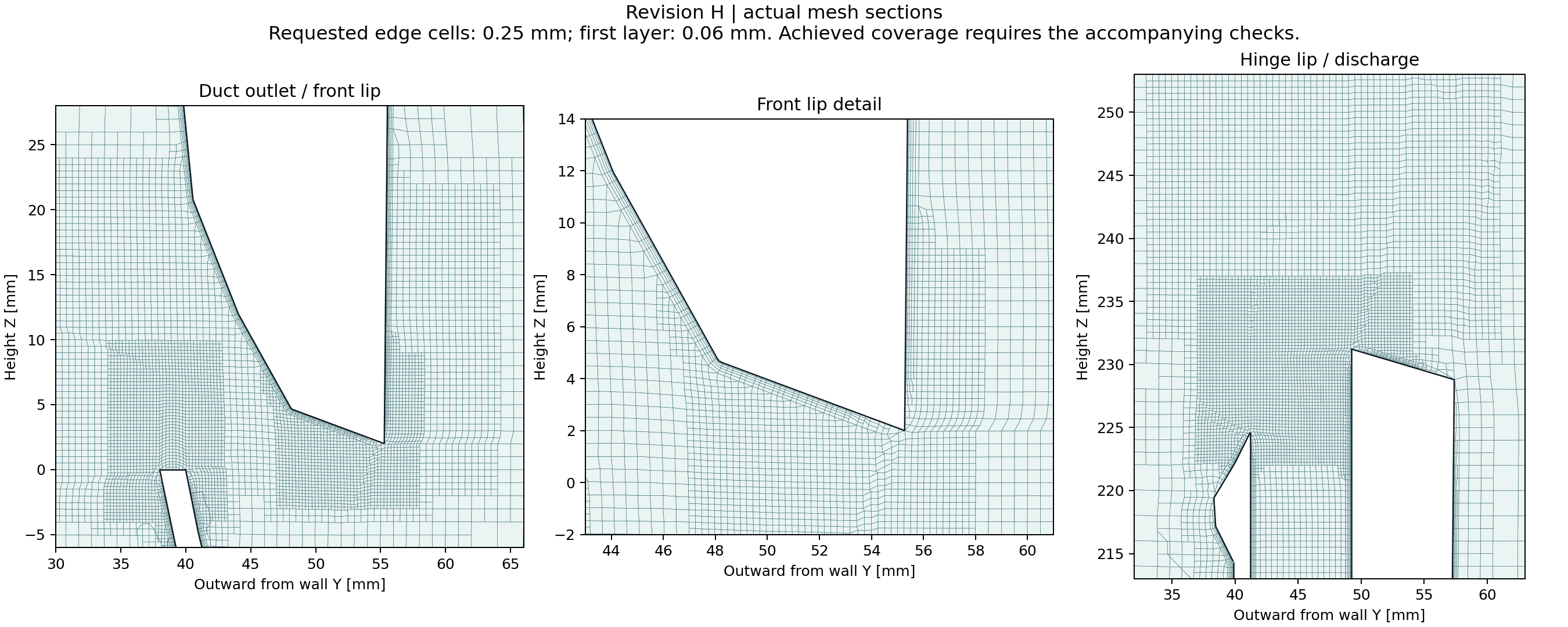
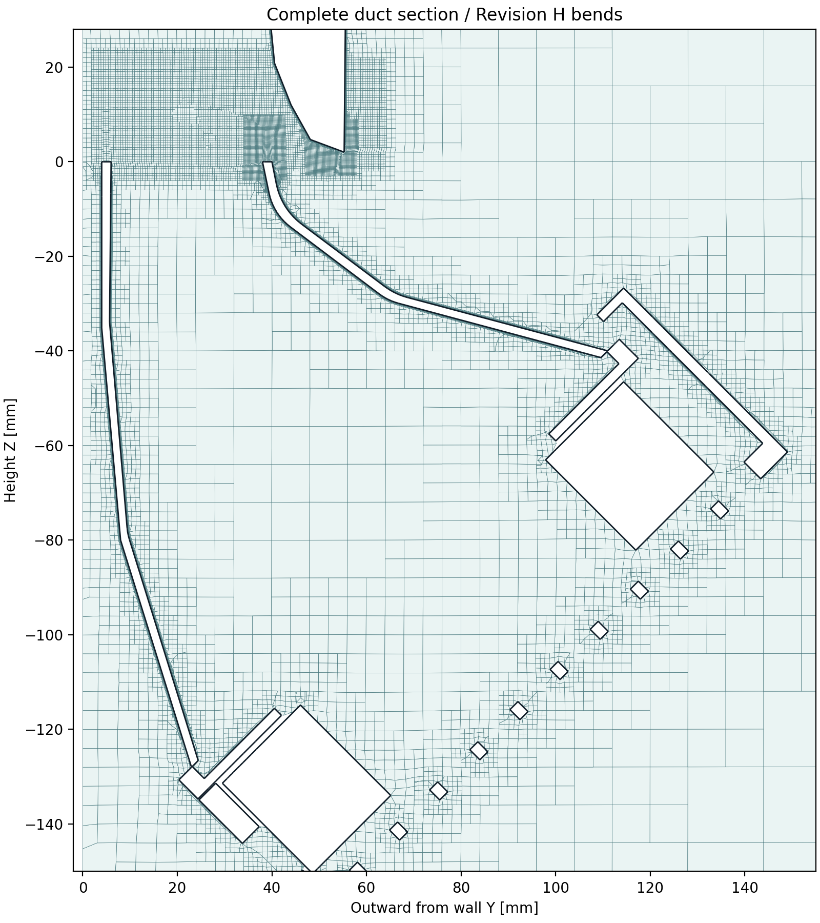
The geometry is the installed Revision H STEP export, including its curved duct transitions. This is separate from the earlier 836,278-cell Revision F study and the minimalist model. The laptop silhouette and internal passages remain approximations.
View the complete duct section
What passed, and what did not
| Geometry and surface | 14 installed solids checked against native CAD; a single closed, valid fluid solid and a non-self-intersecting tessellation. |
|---|---|
| Standard mesh check | Pass. One connected fluid region, positive volumes, maximum nonorthogonality 65° and skewness 2.94. |
| Expanded mesh check | Fail. 2,998 low-determinant cells, 78 low-weight faces and 396,528 concave cells. Defects include lip regions. |
| Transient run | The diagnostic restart completed four steps through 0.0203084 ms. The original 2 ms endpoint was not completed. |
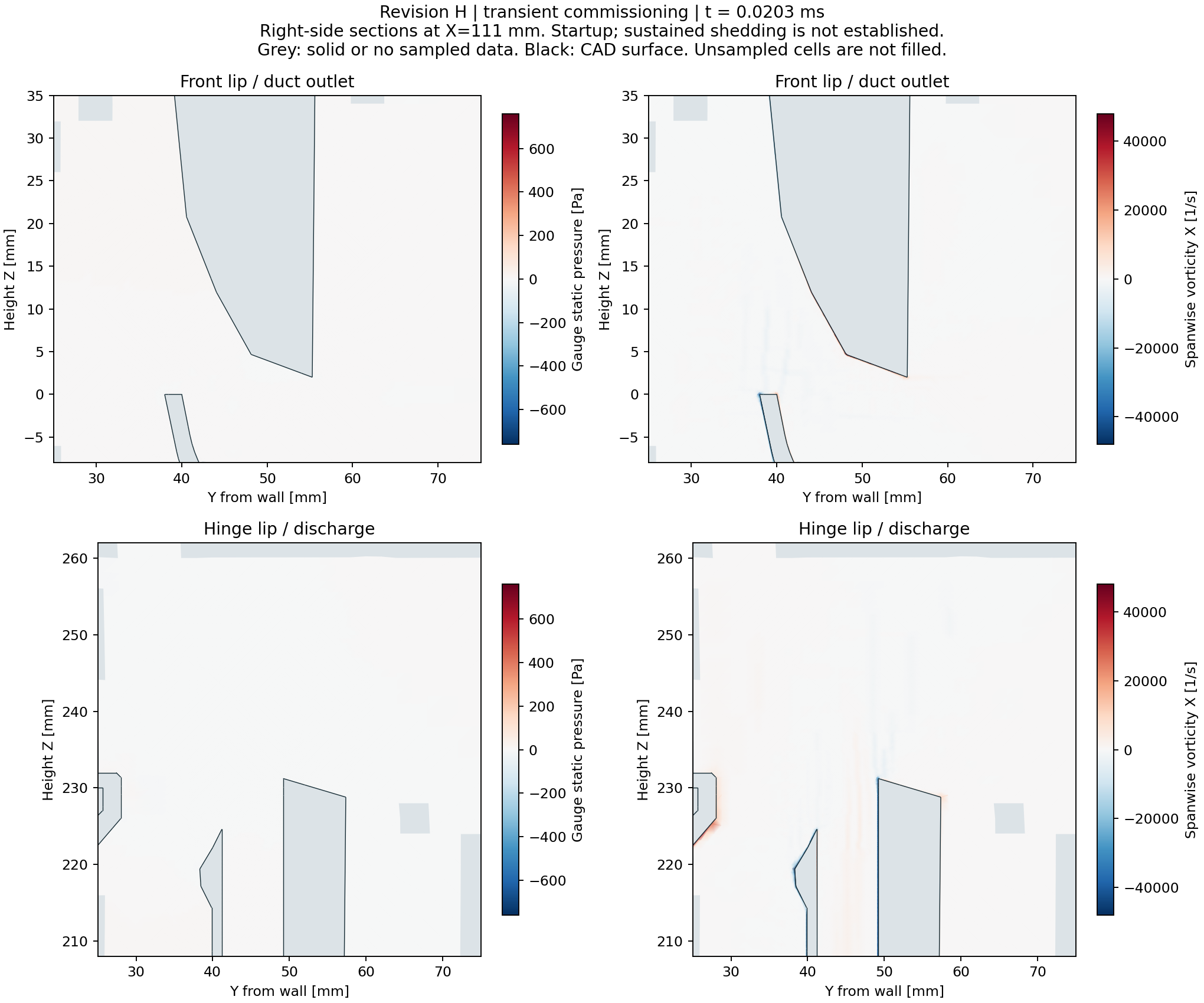
| Shedding and suction | Not established. Startup patterns are insufficient evidence of periodic shedding or settled pressure depression. |
| Numerical independence | Not established. Same-geometry mesh and timestep comparisons remain necessary. |
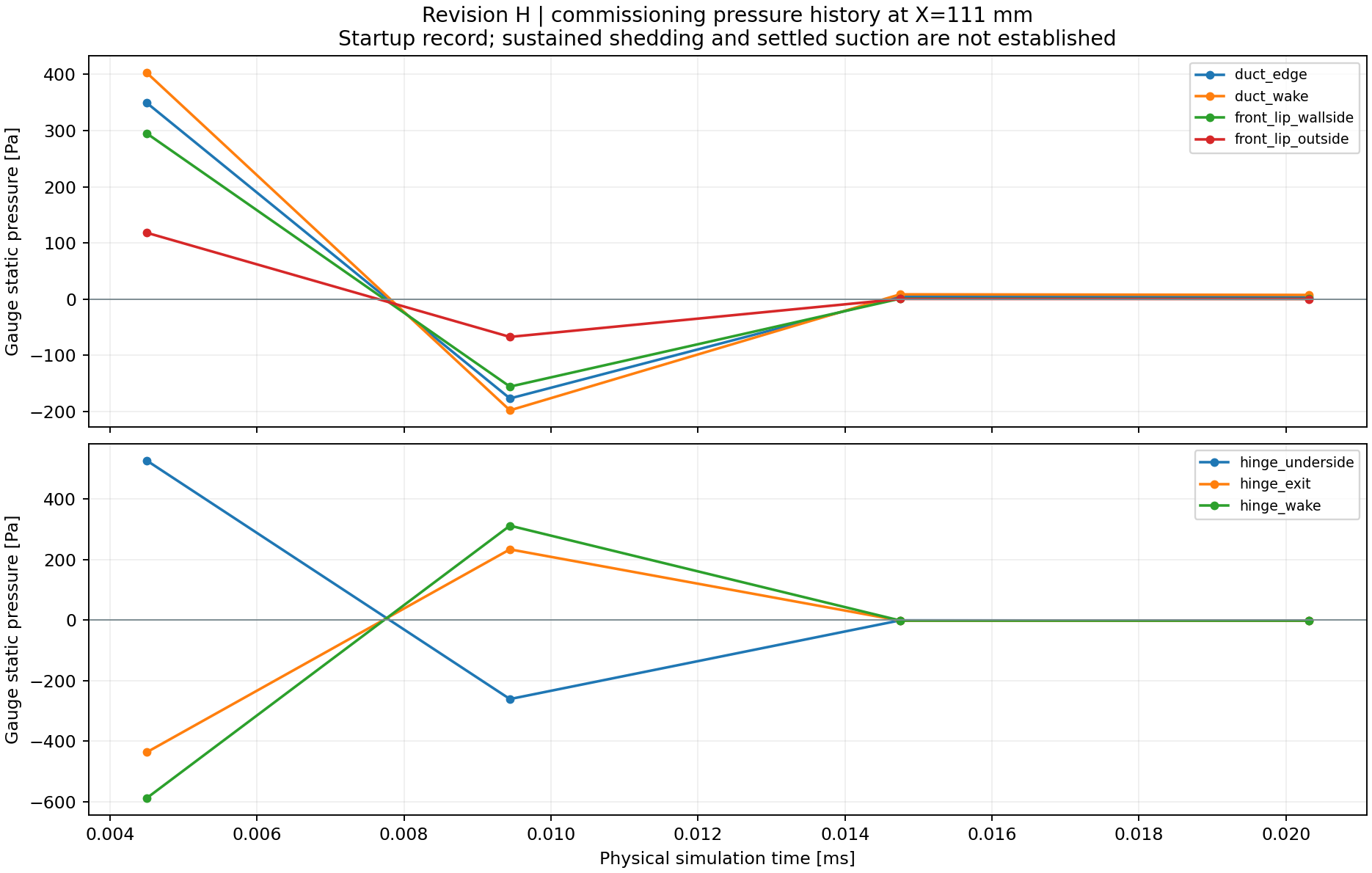
Recorded startup observations
The diagnostic restart completed four steps through 0.0203084 ms in 13.1 minutes, with Courant number at or below 0.5 after loop startup. All 22 probes were valid. Twelve turbulence-bounding events and the mesh quality failures remain unresolved.
These are solver outputs during commissioning. The initial flow was interpolated from the earlier Revision F solution to shorten startup; it is not a settled Revision H flow field. No shedding frequency or Bernoulli conclusion is reported.
What this model can answer
The original pilot was curtailed after the first steps showed costly pressure correction and increasing turbulence clipping. A runtime dictionary-reload error prevented its requested checkpoint. A diagnostic restart uses fixed settings, every-step field output and a 0.02 ms endpoint. This is far too short to establish a flow pattern or frequency.
The transient SST URANS solve records pressure, velocity, vorticity and Q, with probes every step. The original section interval was 0.1 ms; the diagnostic restart records sections every step. A useful shedding result needs settled flow followed by many repeatable cycles, plus mesh and timestep checks. Negative static pressure by itself does not identify a Bernoulli mechanism; fan forcing, acceleration, losses and separated flow must be considered together.
All four fans use nominal 10 Pa constant-force actuators. Fan curves, grille and fin resistance, and internal laptop passages are uncalibrated. The traced laptop profile has approximately ±2 mm uncertainty and intake positions ±4 mm. Finer cells do not remove those geometry uncertainties. This study contains no temperature prediction or hardware validation.
GPU acceleration
The current job uses eight CPU workers in the installed Windows OpenFOAM runtime. The machine has an RTX 3080 Ti with 12 GB VRAM, but no working GPU solver backend has been established. OpenFOAM can offload algebraic solves through an external solver and GPU-enabled PETSc; installation, correctness checks and a case-specific benchmark are still required. The mesh generator does not automatically benefit from that route.
Technical references: OpenFOAM external solver interface · PETSc GPU support · NASA verification and validation guidance