MECHANICAL PROTOTYPE · SEPTEMBER 24, 2026
A floating cradle for a squash ball.
Two TPU pieces. Six curved ribs. The ball rests in an inner cup suspended above an open base, with three different rib geometries arranged in opposing pairs.
Calculated prototype, awaiting a printed load test. Assumes a 40 mm ball and four feet. Actual TPU, ball-holder clearance and corner loads are not yet confirmed. The 20 kg case is an illustrative loaded setup, not a measured AMS configuration. Height is 29.3 mm for the TPU itself, or 56 mm including the full ball, before deflection.
01 / INSPECT THE GEOMETRY
ACTUAL STL MESHESLoading model…
Drag to orbit · scroll/pinch to zoom. Teal: cradle and ribs. Gray: base and catch stop. The ball is a reference only. Geometry is shown unloaded; the calculator does not deform this view.
02 / LOAD & DEFLECTION
1.00 = equal load · 1.30 = a corner carrying 30% extra
Estimated immediate cup sag
— mmLoading analysis…
*Four equally loaded feet, without squash-ball compliance. This is an undamped, linear estimate, not a measured resonance or an isolation rating.
03 / WHAT THE CALCULATION MEANS
CURVED-BEAM MODELThe ribs are 4 mm wide × 10 mm deep. Their centerline lengths are approximately 16.1, 18.7 and 21.8 mm, each repeated on the opposite side. All six contribute to one coupled suspension; they are not six independently tuned frequency filters.
| Total mass | Modulus | Corner loading | Sag | Stop clearance |
|---|
F = mass × 9.80665 / 4 × corner multiplierdeflection = F / kfₙ = √(4 × k × 1000 / mass) / (2π)
The stiffness comes from a discretized curved-beam model with bending, transverse shear and torsion. It assumes a rigid cup and outer ring, clamped rib ends, and isotropic, linear material behavior. It excludes ball compression, base and cup flexibility, local joint stresses, contact, nonlinear stiffening, temperature and long-term creep. Large predicted movements are extrapolations.
The solver is checked against an exact straight fixed-guided beam solution and a doubled element count. Those checks verify the numerical implementation, not the physical accuracy of the assumptions. The two printed parts are also checked for valid solids and watertight, connected STL meshes.
Why the material field matters: Bambu TPU 95A HF lists 9.8 MPa in XY and 7.4 MPa in Z; NinjaTek Cheetah 95A lists 26 MPa. These are different materials and test conditions. Here 7.4–26 MPa is a sensitivity sweep, not a guaranteed bound for your spool. The ribs print flat, but their mixed bending and torsion still cannot be represented fully by one tensile modulus.
P1S mass specification · Bambu material data · Cheetah material data · Full calculation results
04 / PRINT & ASSEMBLE
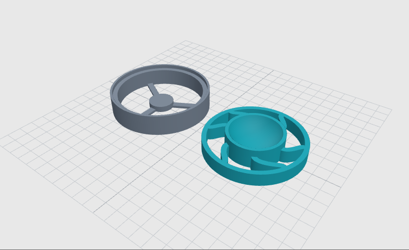
- Print one base and one cradle in their exported orientations, flat sides on the plate. Both pieces are designed to grow upward without support or enclosed bridges.
- For the calculated geometry, use solid ribs: 100% infill, a 0.4 mm nozzle, 0.2 mm layers and at least 4 perimeters. Preview the toolpaths for filled ribs and connected roots. Use the filament maker’s TPU settings.
- Place the cradle’s outer ring into the base’s shallow socket. The ring rests on a shoulder 14 mm above the table; it has 0.25 mm radial clearance. This is a gravity-seated joint, not a snap lock. Lift the assembly by the base.
- Seat the ball in the bowl. Its lower third is cradled, but it is not captured above its equator. Check that the existing upper ball holder clears the cup and rim throughout movement.
The center stop starts 9 mm below the cup. Three floor spokes connect it to the base. It should carry no load in normal use; contact bypasses the suspension.
05 / PROVE ONE FOOT FIRST
Before printing all four, load one assembled foot through an actual ball with 3.24 kg for the equal-load bare-printer case, or the measured mass at your heaviest corner. Keep the weight stable and centered.
- Measure the cup underside height unloaded and after 1 minute under load. Their difference is the actual sag.
- Repeat after 1 hour and 24 hours at the intended temperature. Check the clearance under the cup, cracking, layer separation and sideways tilt.
- A provisional acceptance target is at least 3 mm of remaining stop clearance under the heaviest corner after settling. This margin is a design target, not a validated lifetime limit.
- Use
k = applied force / measured sagto calibrate the next rib revision. Compare table vibration and printer rocking before claiming improved isolation.
TPU can creep. Long-term settling and horizontal/rocking modes remain unverified. Randomly different ribs do not guarantee broadband isolation.
06 / FILES & REVISION RECORD
P01Millimeters throughout. Two STL files make one foot; print four of each for the printer. The bundle includes individual STEP files, editable CadQuery source, shared dimensions, the beam solver and its results.
P01: 40 mm provisional ball; 80 × 29.3 mm TPU envelope; 10 mm-deep ribs; 9 mm unloaded travel. The initial 6 mm rib study was rejected because it could reach the stop in the heavier load cases. No tuned mass absorbers are included in this first prototype.