 thereprocase
PRINTABLE HARDWARE / OPEN ENGINEERING
A place for
every spool.
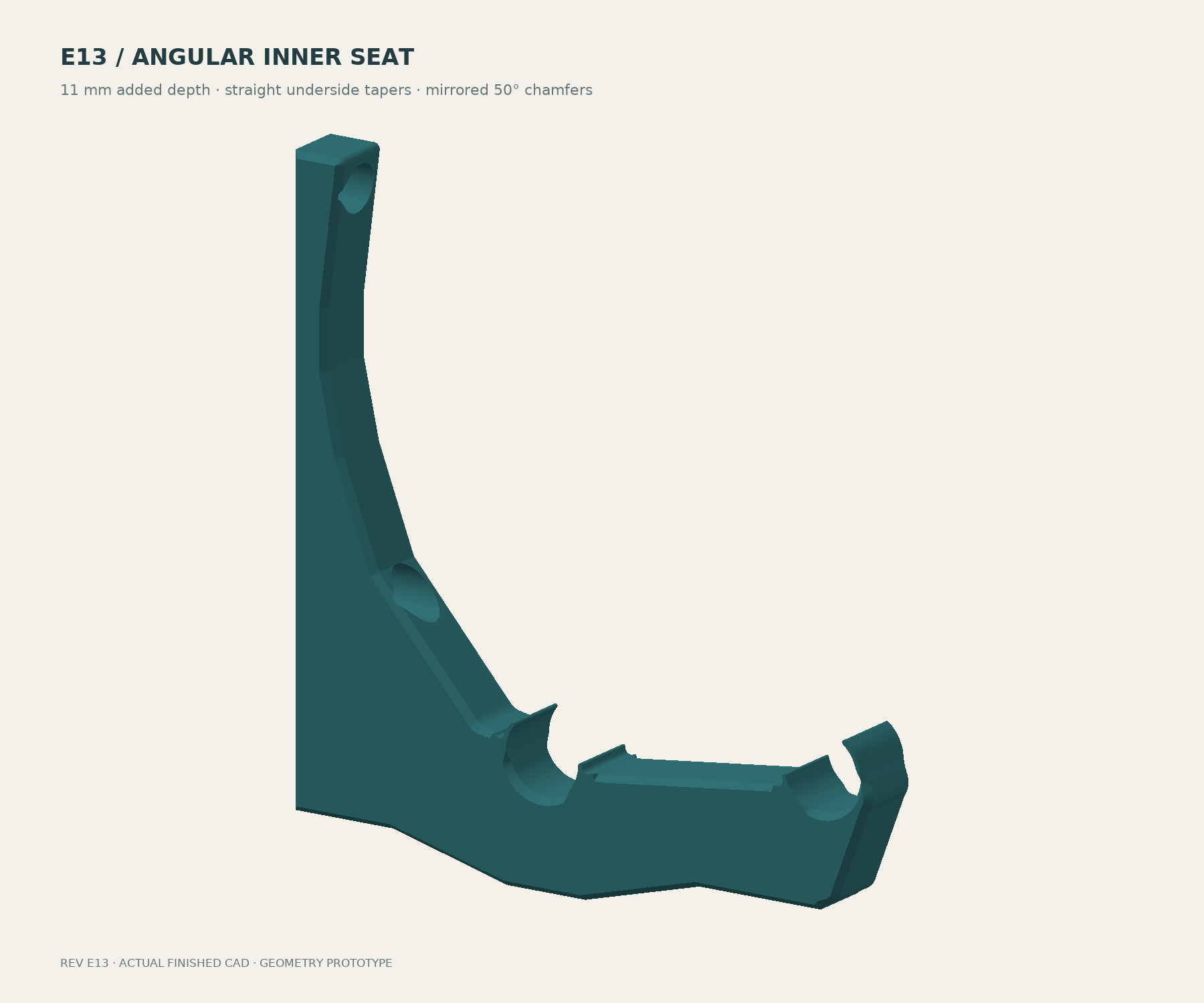
A wall-mounted, two-rail rack built around a compact printed bracket. Straight tapers reinforce the inner seat; flexible fingers retain the rods.
The finished shape, the print setup, and the evidence behind both.
Engineering prototype. Physical fit, hot-load and lifetime qualification remain.
- Print envelope
- 207.51 × 219 × 24 mm
- Added seat depth
- 11 mm
- Broad-face chamfers
- 50° above the bed
01 / STRAIGHT LINES, CAREFUL DETAILS
GEOMETRY CHECKEDStrength follows the shape.
Two long, straight flanks lead into a short flat underside. The 11 mm reinforcement is only 1.5 mm deeper than the curved E12, with a broader taper into the knee and outer arm.
Small corner blends and mirrored chamfers finish the edges. The original flexible fingers, relief pockets, screw access and rod positions stay in place.
- Flanks
- 41 mm horizontal run · about 15°
- Flat underside
- 28 mm long
- Inner-center section
- 30 mm deep
- Nominal rod seat
- 26.0 mm for nominal 25.4 mm stock
Measure the actual rods and print a fit coupon before making the rack.
Rod fit coupons & measurement plan ↗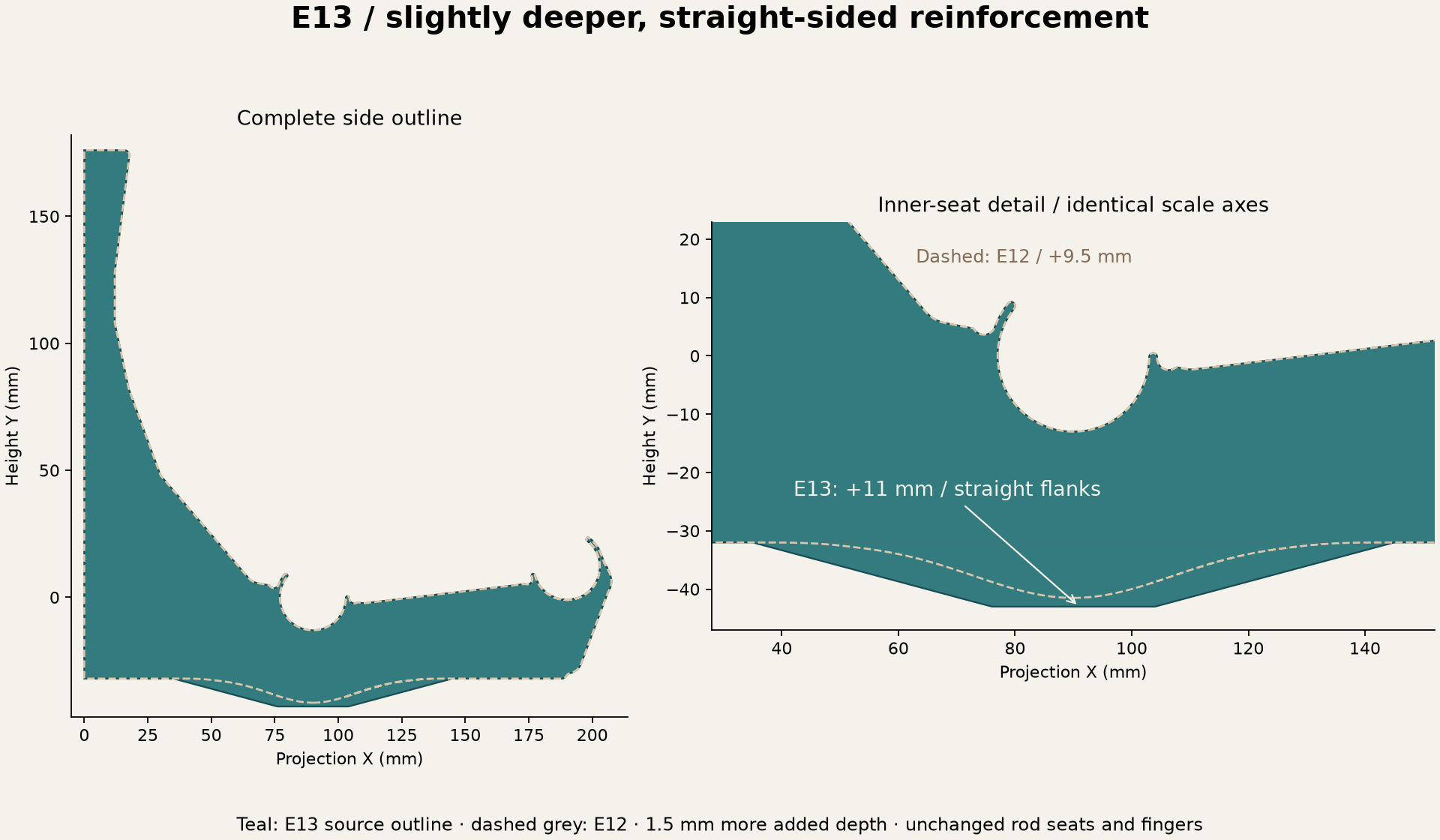
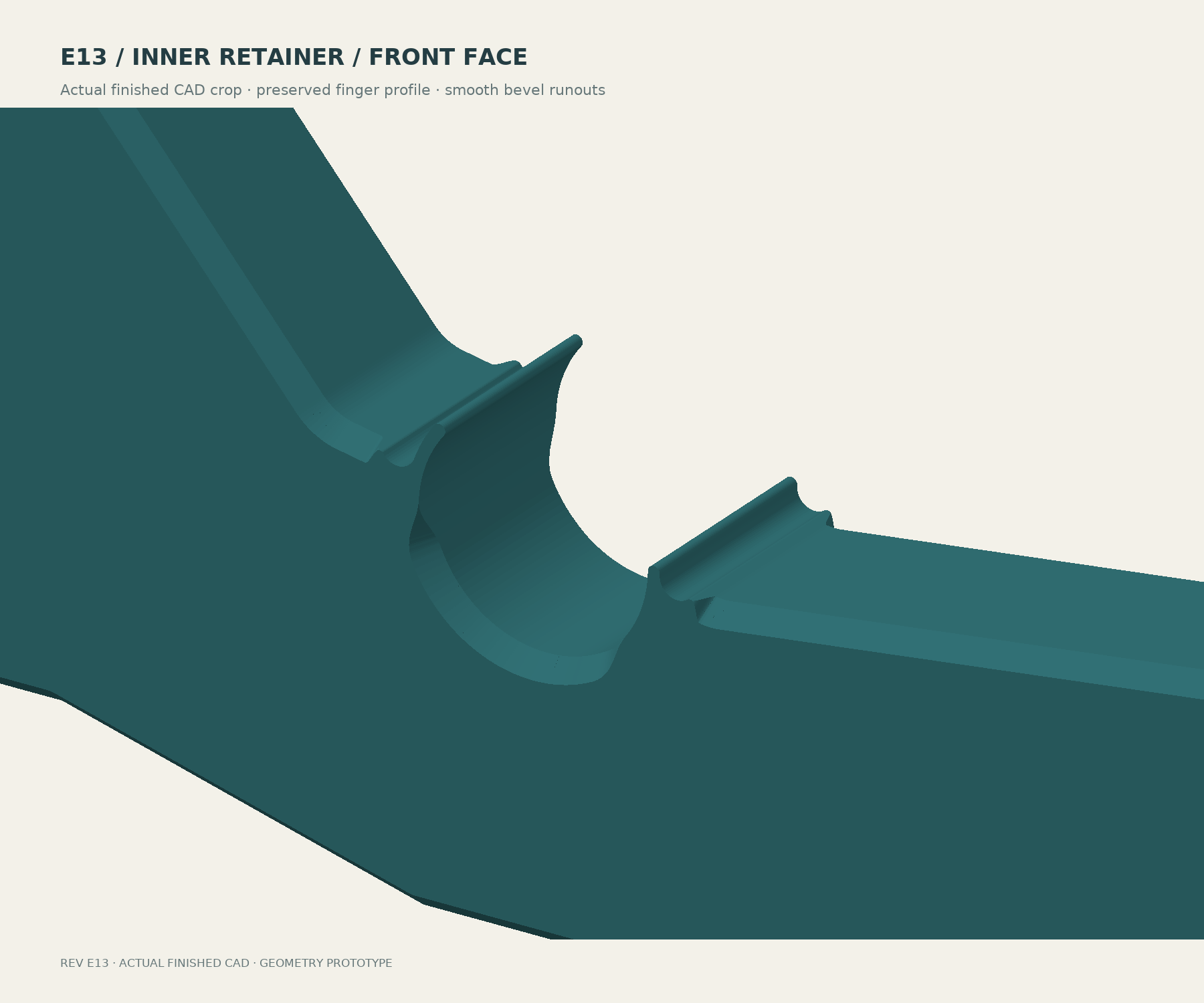
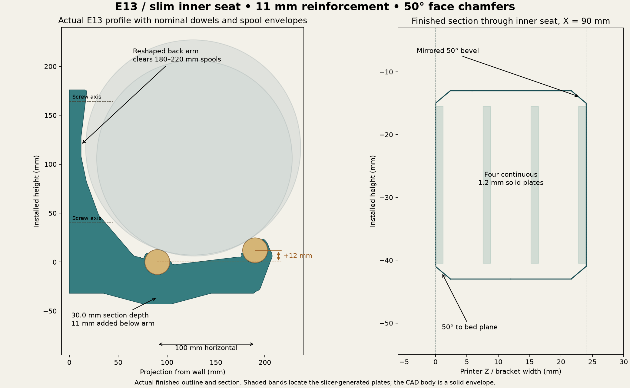
CAD checks pass: one valid body, two aligned helpers, mirrored chamfers, preserved finger geometry and 322 nominal spool-clearance cases. These checks do not establish printed fit or snap force.
02 / INSIDE THE LOAD PATH
REFINED 3D ANALYSISBetter across the seat, knee and arm.
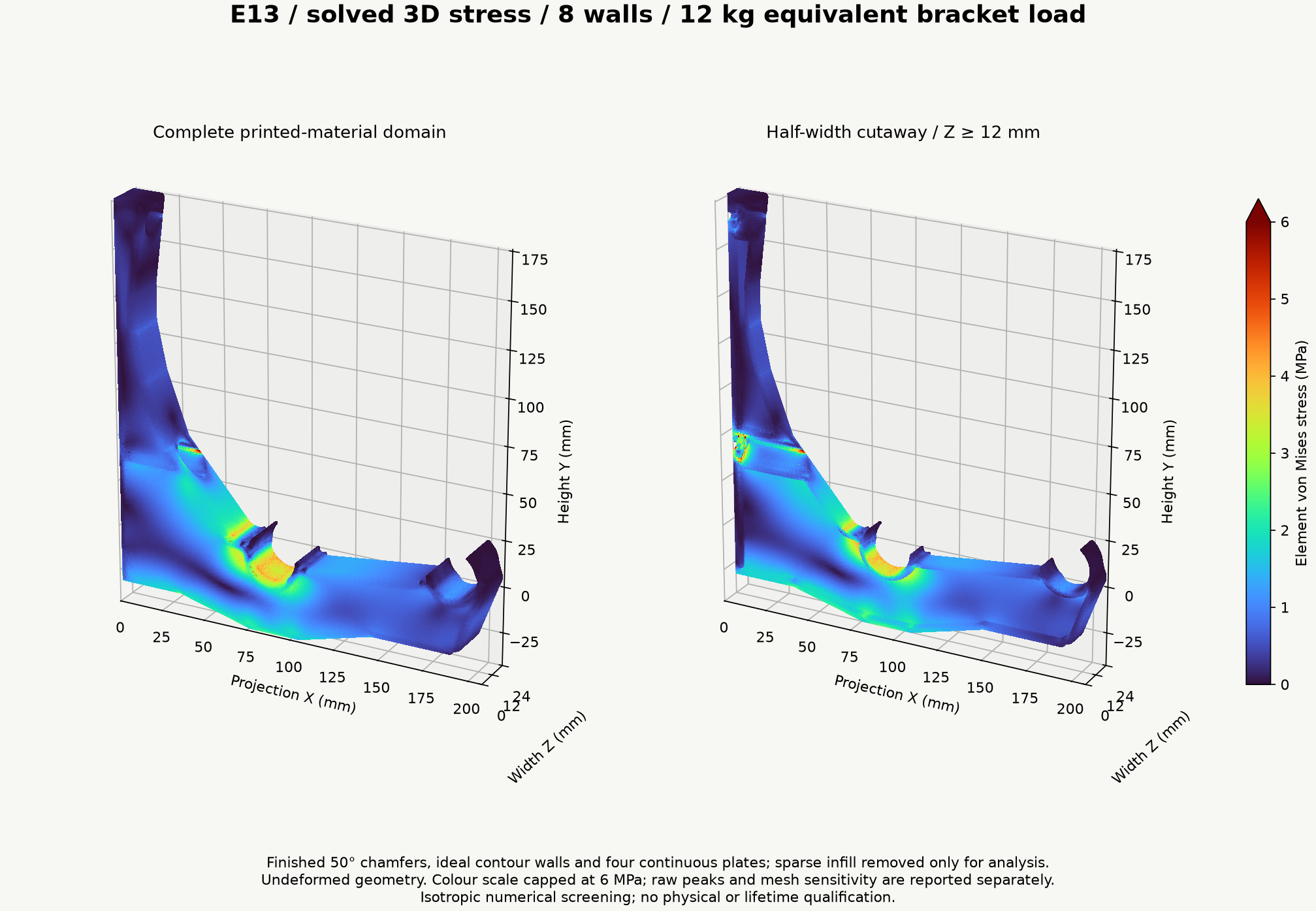
The E13 model includes the finished chamfers, contour walls, four continuous solid plates and screw tunnels. It uses compression-only wall contact and rigid washer and shank restraints. Sparse infill receives zero structural credit.
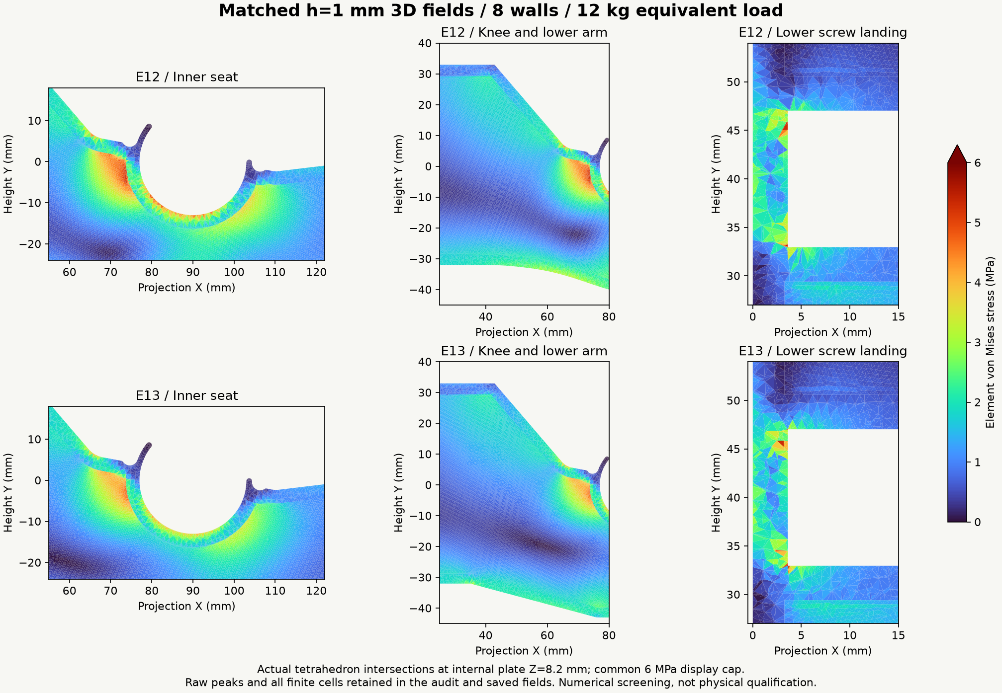
The comparison below uses volume-weighted 99th-percentile stress in matching regions at the same nominal 1 mm mesh size. The reference load is 12 kg equivalent per bracket; it is an analysis case, not a released load rating.
| Region | 8 walls | 10 walls |
|---|---|---|
| Inner seat | −13.28% | −13.22% |
| Knee | −9.31% | −10.37% |
| Outer arm | −19.41% | −20.24% |
| Lower screw landing | −0.17% | +0.93% |
| Upper screw landing | +1.17% | −1.12% |
Resolution where the geometry matters.
Three global mesh levels—2, 1.5 and 1 mm—resolve the complete bracket. The finest models contain 757,028 tetrahedra at 8 walls and 787,137 at 10 walls.
The last refinement changes front movement by about 1.9% and the near-seat stress statistic by 1.1% or less. Independent force, moment and free-residual checks pass.
The E12 eight-wall baseline required a different mesher. Nominal resolution and physical inputs match; individual meshes differ. The full audit records that limit.
Mesh refinement, regional windows & raw peaks ↗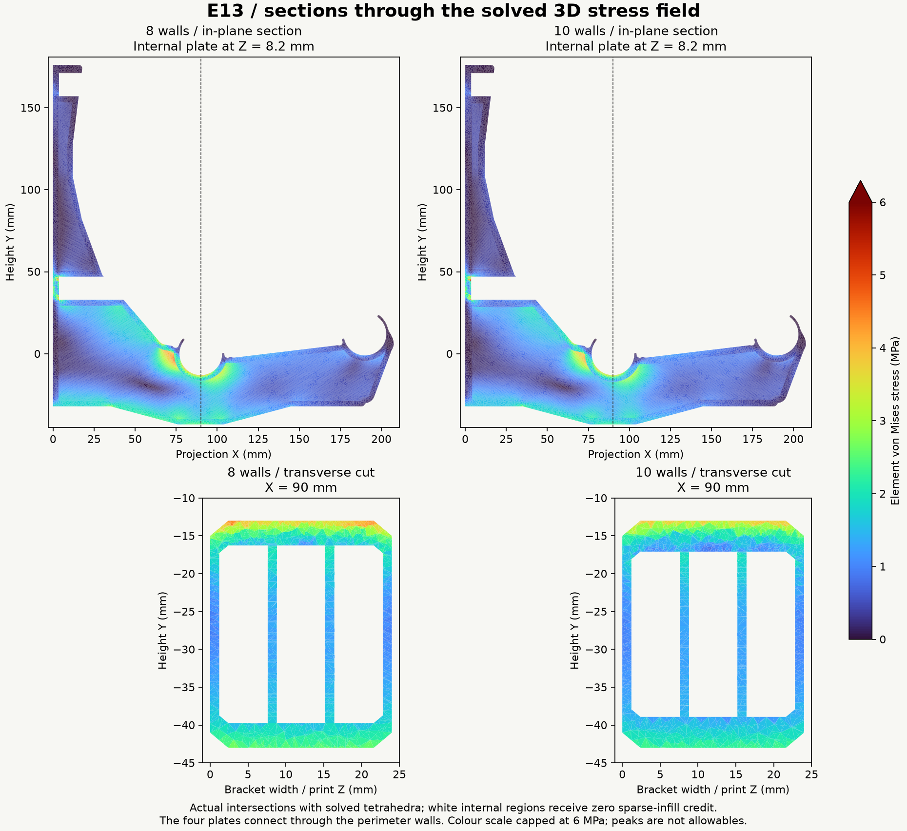
Local peaks remain. Isolated maxima still change with mesh refinement; screw-landing stress is essentially unchanged. Figures use a common 6 MPa display cap, while saved fields retain every finite element and its raw stress. These results do not establish rupture strength or long-term print performance.
At the reference load, grade-specific room-temperature moduli give about 0.627 mm initial front movement for the 8-wall PLA case and 0.838 mm for 10-wall PETG. These are bracket-only model results. Rod sag, mounting movement, heat and creep still need to be accounted for.
03 / PRINT THE STRUCTURE
ORCASLICER PATHS CHECKEDFour solid bands. One aligned object.
Print on the supplied broad side so the main bending load lies in the layer plane. Import the STEP as one object with three aligned parts.
- Set up the body. Use 0.20 mm layers, a 0.4 mm nozzle, Arachne walls and Everywhere gap fill. Start with 8 walls for the PLA prototype or 10 for PETG.
- Keep the four solid bands. Use six top and six bottom layers. Convert both helpers to 100% infill modifiers at their supplied positions; keep body infill at 15%.
- Inspect the sliced paths. Check the bands, seat walls, flexible fingers, screw lands and access roofs. Calibrate temperature, flow, cooling and bonding for the actual filament.
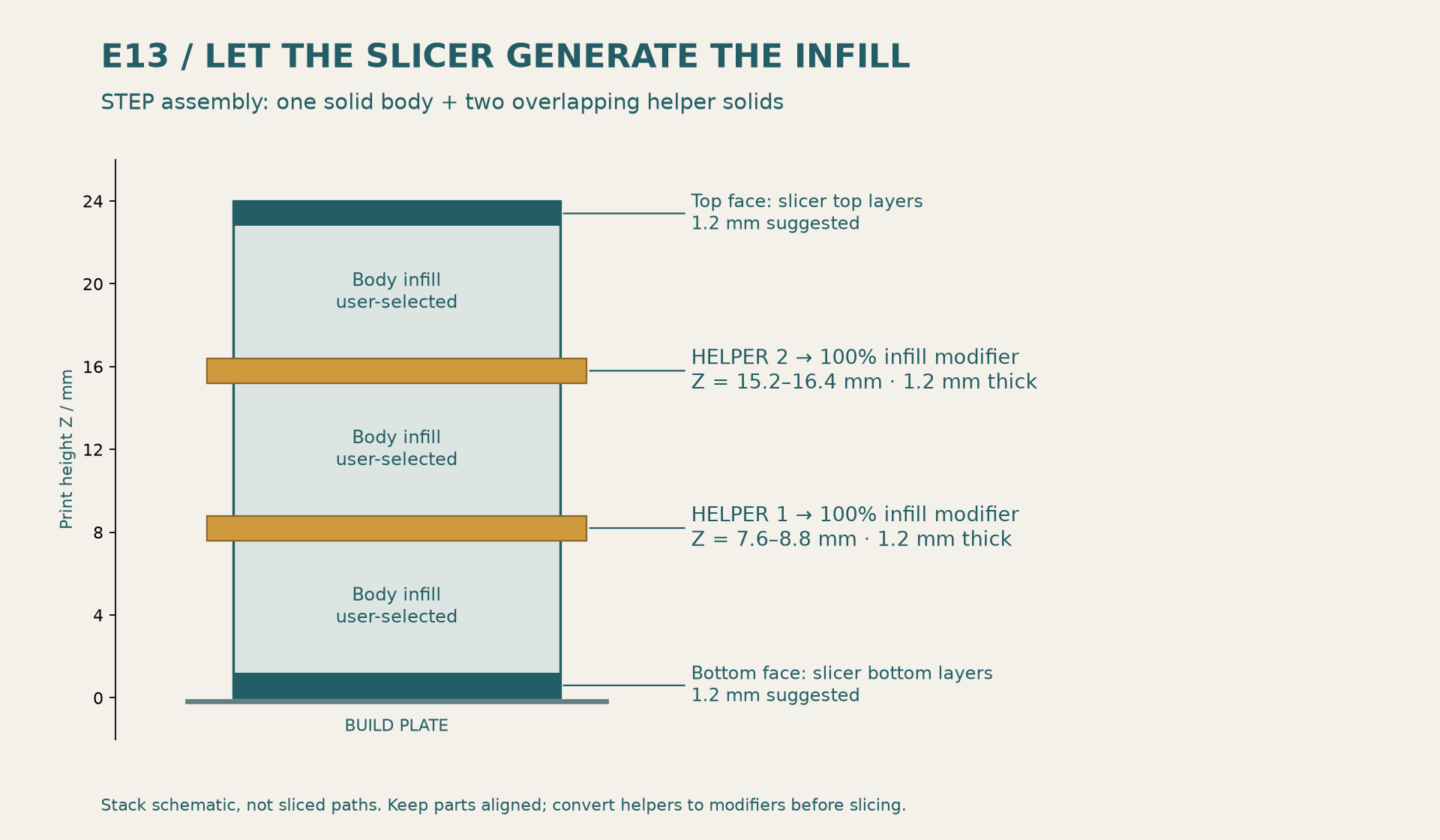
STEP stores alignment, not slicer settings. Convert both helpers to modifiers. They must not print as extra exterior slabs. Check the 207.51 × 219 mm footprint against your printer’s usable bed area.
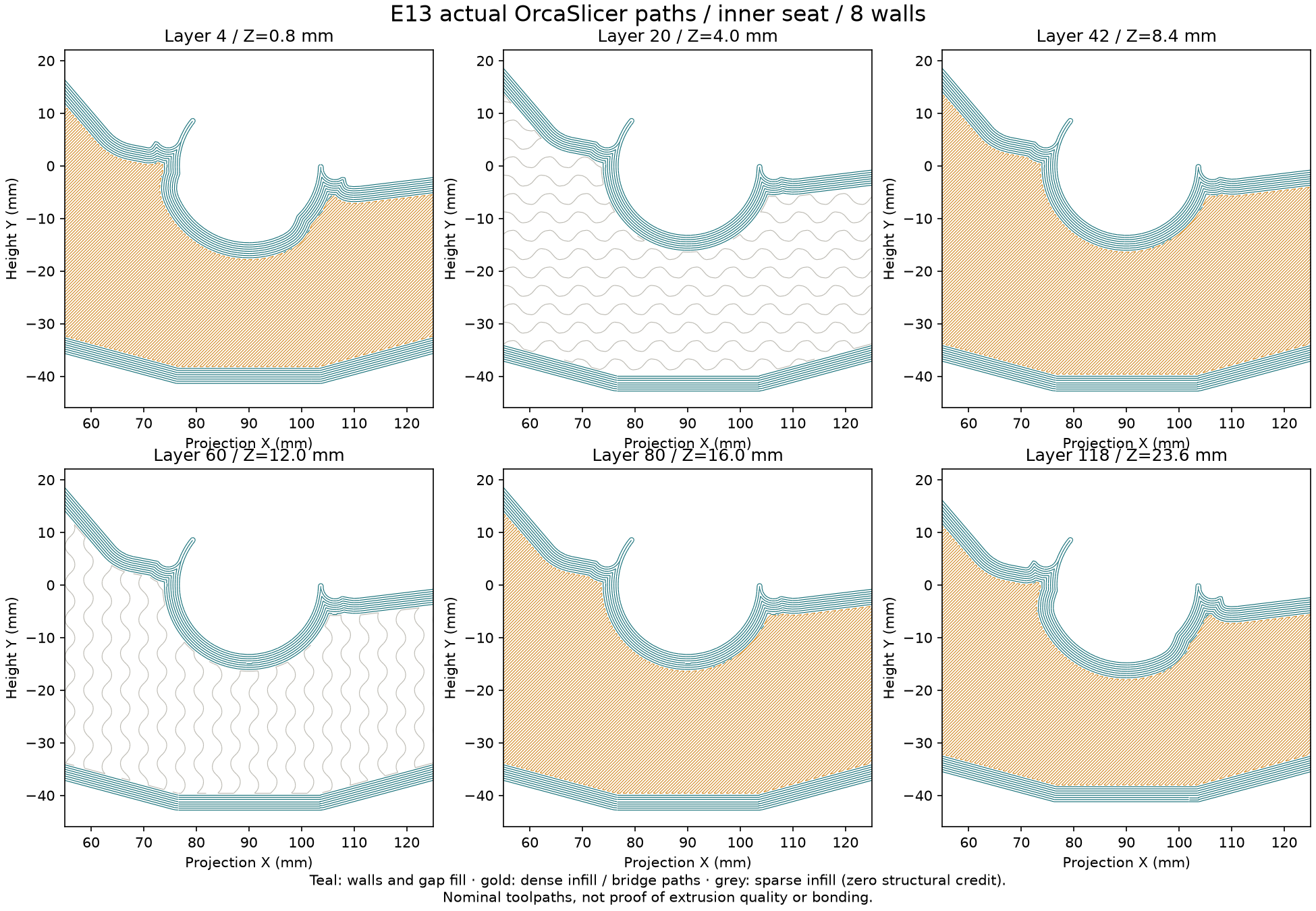
Both reference slices pass all 120 layers and all 24 intended solid-band layers, with sampled checks of the full planes, seat walls and fingers. Slicing does not qualify physical bonding, bridging or curling.
Detailed print handoff & verification records ↗04 / TAKE IT TO THE WORKBENCH
E13 DOWNLOADSStart with the assembled STEP.
The main body and both infill helpers retain their alignment. The STL bundle is a fallback if the importer loses those parts.
STEP: 15.25 MB · millimeters · geometry only. STL bundle: body-only.stl, helper-1.stl and helper-2.stl with setup notes.
05 / AN OPEN PROJECT RECORD
DESIGN → ANALYSIS → PHYSICAL CHECKSThe earlier shapes stay on record.
E11 explored a deeper reinforcement. E12 reduced the protrusion. E13 adds straight tapers and a little depth, then follows the change through section checks, slicer paths and refined stress fields.
Next: prove the printed rack.
Check rod fit and snap retention, immediate loaded movement, dowel sag and wall contact. Measure drift under the intended warm service conditions and inspect for cracking or layer separation.
No physical proof test or lifetime qualification is claimed. All figures and downloads on this page come from the published E13 revision.