STL RECONSTRUCTION · MODIFIER BODIES · FEA · TOOLPATHS
Designing the material distribution inside an FDM part.
An aligned helper body can turn a small region of a print into solid infill, add walls around a fastening point, or create a continuous internal plate. That makes internal material placement an explicit design variable alongside the outside shape.
These projects connect that control to editable CAD, structural comparisons and the extrusion paths produced by the slicer. The useful result is a reproducible design that includes its reinforcement regions and a record of what they were checked against.
Kraken body baseline. Dense root masks use 4 walls / 100%; selected wall paths use 4 walls / 15%.
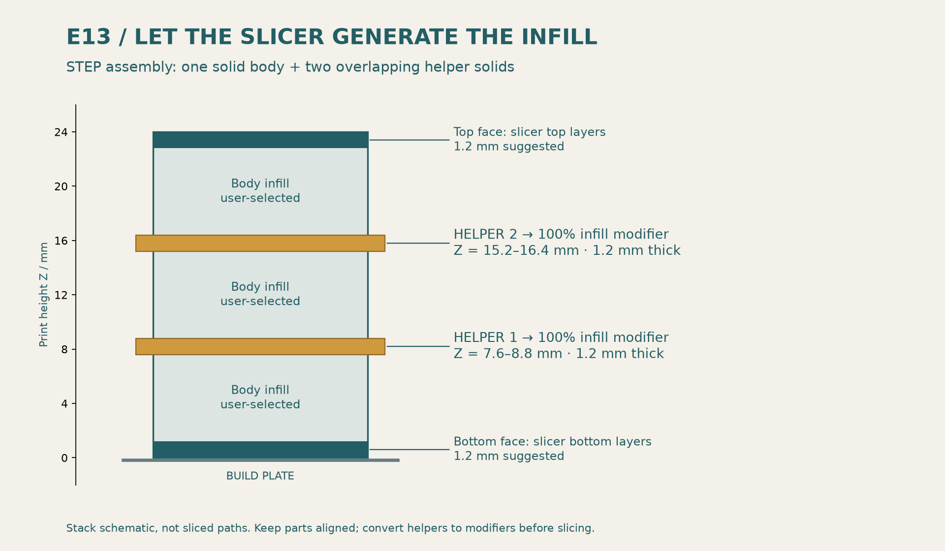
E13 continuous solid plates. Two internal helper bands complement the top and bottom skins.
Orca estimate for both final Kraken ASA body/bar plates, including brims. Full-size physical acceptance remains.
01 / FROM AN STL TO EDITABLE GEOMETRY
Recover the features that determine fit.
A mesh records a surface as triangles. Reconstructing its functional features gives those surfaces editable dimensions and relationships: bearing seats, mounting lands, walls, pockets and mating joints. The Kraken work uses measurements from the source geometry to build native CAD and then checks the resulting interfaces.
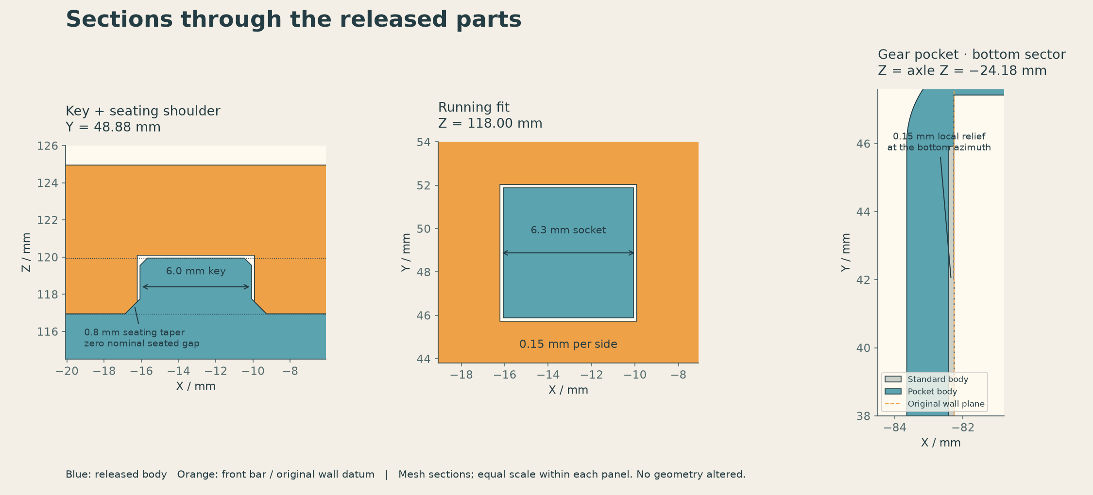
This is what makes tracing useful for a remix: a clearance pocket, front-bar split or reinforcement region can follow the reconstructed design parameters. Each change can be checked against the original interfaces and the accepted release.
The accepted pocket cut5 pair passes 109 right-side and 101 left-side hardware checks at a 0.05 mm digital comparison scope. The largest delivered probe distance in that table is 0.049886 mm. These are sampled digital checks; printed fit also depends on the material, machine and process.
The public rebuild produces native solids from the included source. Its reproduction check compares those solids and exports with the accepted files. Reference mesh fixtures serve as validation inputs. This is a documented reconstruction workflow; the repository does not provide a general automatic STL-to-parametric-CAD converter.
Interface checks and reconstruction limits ↗ · Editable CAD source ↗
02 / HELPER BODIES CONTROL THE SLICER
Keep the reinforcement geometry with the part.
Each helper is a separate, aligned volume. In the slicer it becomes a modifier: inside that region, the process uses the assigned wall count or infill density. The surrounding part keeps its baseline settings. The helper’s overlap, position and precedence determine which settings reach each region.
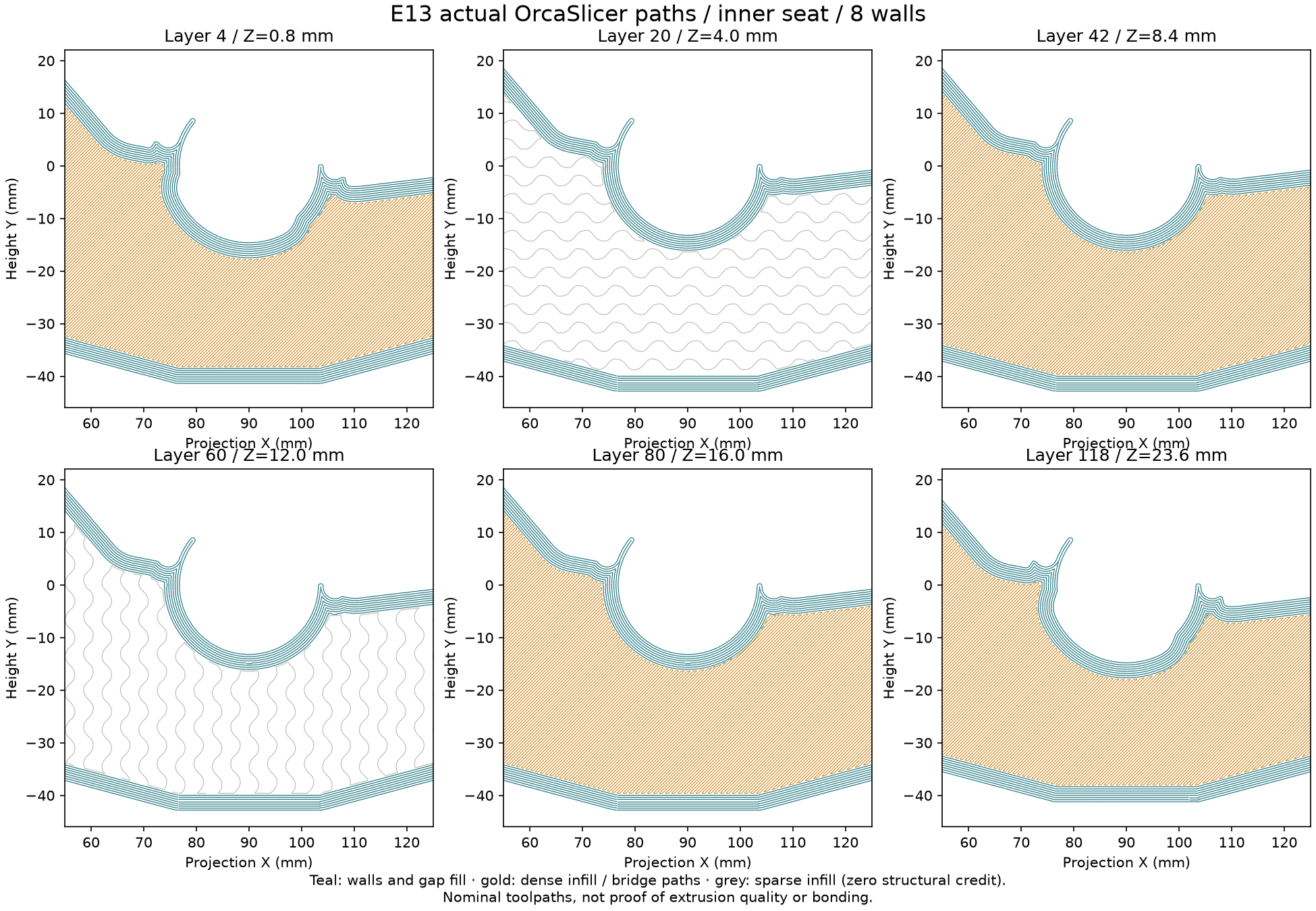
For the Kraken ASA bodies, seat, fastener and key-root masks raise the process from 2 walls / 15% rectilinear to 4 walls / 100%. Separate wall-path masks use 4 walls / 15%. Dense masks take precedence where those regions overlap. Front bars use their own uniform 4-wall / 30% recipe.
The E13 rack uses a different construction: aligned helper bands create two internal 1.2 mm solid plates, while top and bottom skins provide two more. This gives the load-bearing section continuous material at selected depths, with sparse regions between them.
The practical opportunity is to tune reinforcement independently of the visible part: adjust a band depth, enlarge a root region, or compare wall counts while keeping the mating surfaces fixed. Those edits still need new section, slice and structural checks.
STEP preserves the helper alignment, but does not store the intended slicer settings. Convert the E13 helpers to 100% infill modifiers after import. Kraken’s supplied editable 3MF projects already contain the modifier settings and were checked after reopening.
03 / CONNECT THE STRUCTURAL MODEL TO THE PRINT
Model the material that the recipe actually supplies.
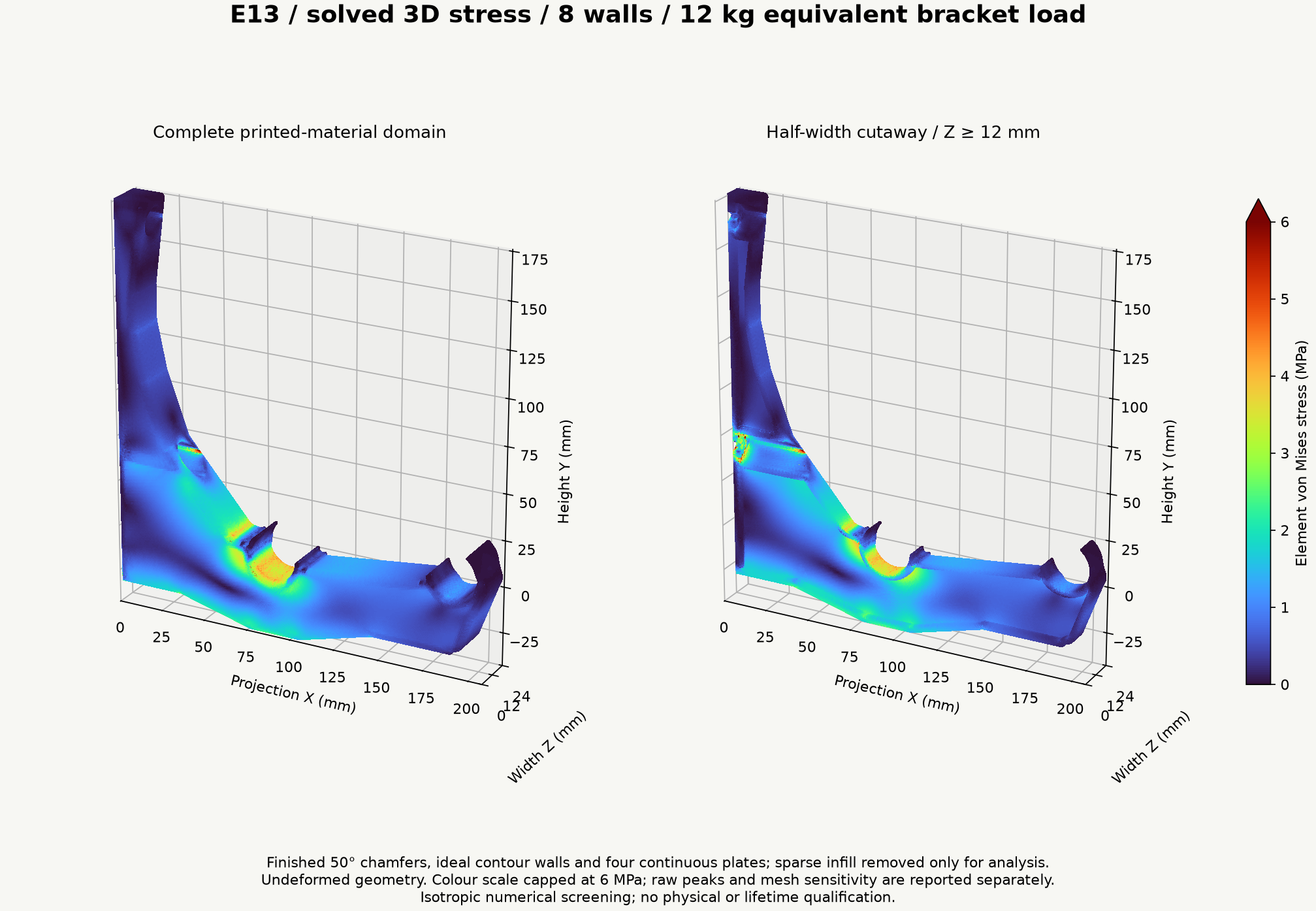
The E13 study explicitly represents contour walls, four continuous solid plates and screw tunnels. Sparse infill receives zero structural credit. Compression-only wall contact and rigid washer/shank restraints define the mounting model.
At matched nominal 1 mm resolution, the eight-wall E13 comparison reduces volume-weighted regional p99 stress by 13.28% at the inner seat, 9.31% at the knee and 19.41% at the outer arm relative to E12. Screw-landing stress changes little. The reference load is 12 kg equivalent per bracket; it is a comparison case, not a released load rating.
Three mesh levels support the refinement study. The final step changes front displacement by about 1.9% and near-seat stress statistics by 1.1% or less. Isolated peak stresses remain mesh-sensitive. This is why the plots retain their legends, regional definitions and limits.
The Kraken whole-body FEA did not converge. Its reinforcement recommendation instead uses the documented net-section screen and preserved load strips. No physical stiffness gain or safety factor is assigned from that unconverged solve.
Used this way, FEA helps compare reinforcement candidates, and actual toolpaths check whether the proposed material distribution is present. Printed bonding, fit, warp, creep and proof loading remain physical tests.
E13 fields, refinement and assumptions ↗ · Kraken engineering assumptions and acceptance checks ↗
04 / REPRODUCE THE EXAMPLES
Kraken AMS bodies
Editable native reconstruction, removable bars, local root and wall masks, and reopening-checked ASA projects. The first full-size print and installation remain acceptance steps.
E13 spool-rack bracket
Aligned helper STEP, four solid plates, eight- and ten-wall reference slices, refined stress fields and the E12 comparison.