Gridfinity drawer insert generator
Size a 42 mm Gridfinity insert and divide it into printable tiles.
Loading…
Dimensions and grid placement
Generated tiles
Loading local geometry engine…
Top view, inspection and model details
Dimensions and print notes
Viewer help
Preview tile IDs match the end of the download filenames. Row 1 is at the front; zoom in for crowded labels.
Browser-based compute and render. Geometry is generated on your device; large inserts can take longer.
Top view · placement and cuts
Placement and cuts
Instructions, reference and examples
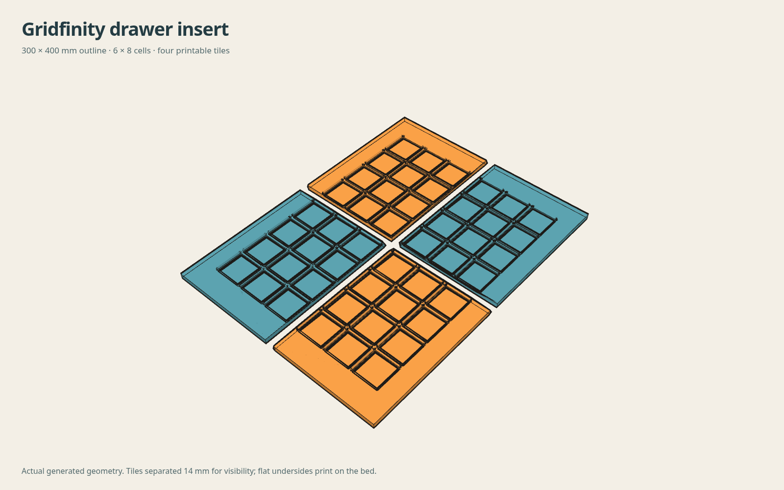
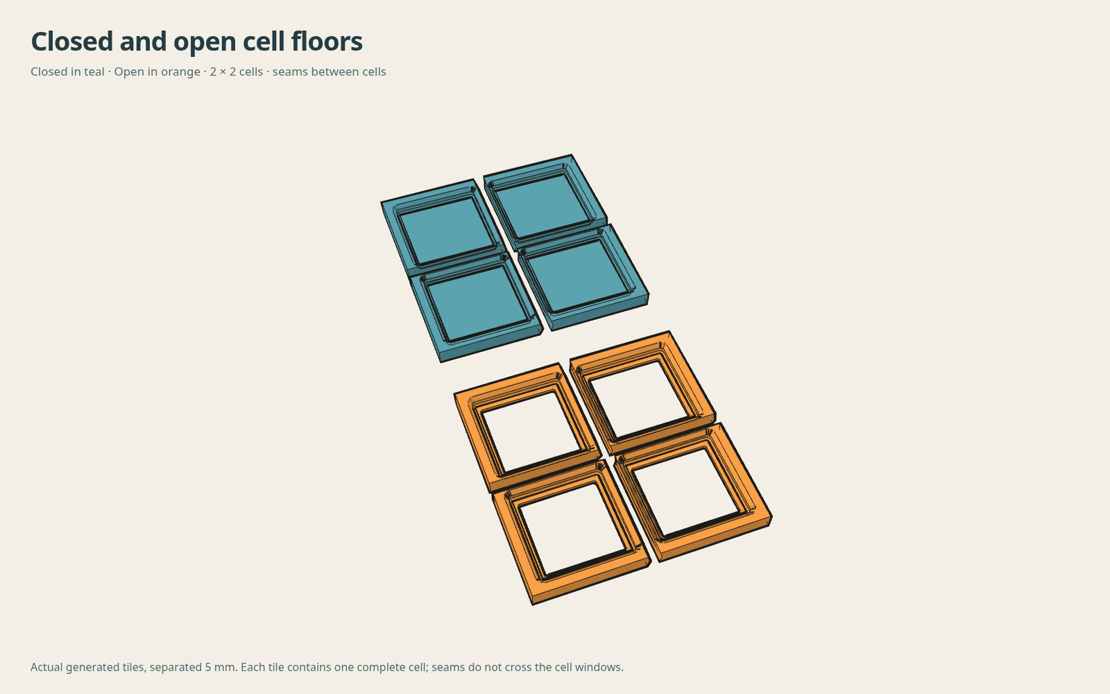
Gluing the tiles
The finished grid is divided by subtracting a 0.15 mm thick V-shaped strip at each seam, with a default 0.8 mm V depth. Half the relief comes off each mating face. Tile positions and the nominal 42 mm grid stay where they were in the finished insert.
This is a sliding-fit allowance for printed faces, not an open weld gap. Dry-press the tiles snugly together and check a bin across the seam. Remove the bin, apply a small amount of CA, and press the joint home while it cures. You do not need to hold a bin or spacer in the assembly.
If the printed trial's cross-seam fit needs correction, adjust X/Y face stock. Positive stock widens the snugly assembled seam pitch; negative stock narrows it. Start at zero and check a small pair before making the full insert.
Download the seam-trial recipe. Check that the flat undersides rest on the drawer floor and a bin seats across the snug dry joint. The assembly preview shows the original model registration and its removed fit-relief strip; it does not shift the CAD tiles to close that strip.
Printing your insert
Each tile is a watertight, connected solid with a 1.2 mm default floor thickness and 5 mm seat region. Closed mode keeps the entire floor; Open mode has 32.5 mm rounded cell windows, with seat ledges and solid glue-edge floor strips retained. The receiver profile follows the reviewed pegboard generator; added seat clearance is independent of drawer edge padding and joint tuning. Downloads place the flat underside at Z=0. Print flat side down. The shallow joints are designed to print without supports. Use your usual filament profile.
STEP exports contain faceted solids matching the generated tile. Generation and exports run locally in your browser using Manifold. Large arrays take longer; Cancel stops the worker. The generator checks connected solids in either bottom mode, closed mesh edges and reference bin-foot interference before enabling downloads. Dimensions and assembly notes · Gridfinity reference.
Set the finished outline, place a 42 mm grid inside it, and divide the insert into flat-printing tiles. Shallow V faces register adjacent tiles for CA gluing; there are no snaps, dovetails or captured connectors.