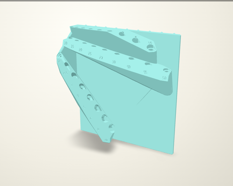
Historical geometry and computational evidence. The owner’s socket-fit trial failed; this full rack has not yet adopted the new guide geometry.
What changed in v2
- A peg in every hole the plate covers: hook pegs every inch across the top row, locking hoops across the bottom row, and gravity-load pegs in the 72 holes between (9 columns × 10 rows). The reviewed peg profiles are unchanged; the back is now their 5.4 mm wall throughout. Hook the top row in, then the intended final motion swings the bottom toward the board. Whole-rack clearance and physical hoop recovery remain unqualified; see the installation audit.
- The solid-infill helpers are braces: a solid web through each row of sockets, a short bulkhead at every socket and a disc round every peg root, instead of padded sleeves.
Original socket design (superseded)
- Every seat is at least four times the key size. Long hex keys and the smallest T-handles get deeper seats so they sit lower.
- Each L-key’s short arm points straight downhill, so a key dropped in at any turn swings to rest. T-handles have no preferred turn, so T3 and up sit in hex-keyed bores clocked to their grip turn.
- The original design used a short neck, a widened chamber and a sloped floor. Owner testing found inadequate centering and rotational restraint; that seating approach is superseded by the straight-guide trial above.
- To take a tool, straighten it, lift it out of its seat, then pull it forward. Every route clears the other tools and a 3″-deep shelf 2″ above.
236 mm wide, on the nine-cell peg pattern (columns at ±101.6 mm) · 178 mm from the board to the furthest tool · 236 mm tall in the print, on its left end.
| Tool | Size | Seat | Turn held by |
|---|---|---|---|
| Hex L-key | 1.5 mm | 12 mm | gravity |
| Hex L-key | 2 mm | 15 mm | gravity |
| Hex L-key | 2.5 mm | 17 mm | gravity |
| Hex L-key | 3 mm | 20 mm | gravity |
| Hex L-key | 4 mm | 26 mm | gravity |
| Hex L-key | 5 mm | 33 mm | gravity |
| Hex L-key | 6 mm | 40 mm | gravity |
| Hex L-key | 8 mm | 50 mm | gravity |
| Hex L-key | 10 mm | 61 mm | gravity |
| Torx L-key | T10 | 12 mm | gravity |
| Torx L-key | T15 | 13 mm | gravity |
| Torx L-key | T20 | 15 mm | gravity |
| Torx L-key | T25 | 18 mm | gravity |
| Torx L-key | T27 | 20 mm | gravity |
| Torx L-key | T30 | 22 mm | gravity |
| Torx L-key | T40 | 27 mm | gravity |
| Torx L-key | T45 | 31 mm | gravity |
| Torx L-key | T50 | 35 mm | gravity |
| T-handle | 2 mm | 71 mm | set by eye |
| T-handle | 2.5 mm | 32 mm | set by eye |
| T-handle | 3 mm | 12 mm | hex-keyed, ±19° |
| T-handle | 4 mm | 16 mm | hex-keyed, ±12.3° |
| T-handle | 5 mm | 20 mm | hex-keyed, ±9.3° |
| T-handle | 6 mm | 24 mm | hex-keyed, ±7.5° |
| T-handle | 8 mm | 32 mm | hex-keyed, ±5.4° |
| T-handle | 10 mm | 40 mm | hex-keyed, ±4.2° |
Printing
- Original v2 coupon (history) (coupon STL, plain 20%, about 113 g / 5h 26m 9s). It is cut from the final model and prints the same way. The end slice hangs on the board from the top of the left peg column and holds Torx T10/T15, hex 1.5/2 and T-handles T2, T2.5 and T3; drop the tools in, knock the board, pull them out. The PEGS strip is the rest of that column down to the locking hoop, so you can feel the gravity-load pegs and the hoop snap. Blocks T5 C and T5 F key the T5 shaft to its corners and to its flats: the one that holds the bar at the right turn tells you how your handles are made. This archived full part assumes corners; the owner has since confirmed flat-to-flat handles.
- Archived full part (older seats): open the Bambu Studio / OrcaSlicer project with solid-infill zones. It is the body plus brace zones at 100% infill (socket row webs, socket bulkheads, peg roots), about 636 g / 1d 6h 26m 33s. A lighter alternative is the print-oriented STL at plain 20% infill, about 554 g / 1d 1h 39m 23s. Print it on its left end as oriented, with tree supports on the build plate only (they land under the peg hooks behind the mounting face).
- ASA: use an enclosure and a 5 mm brim. Then paint the debossed size labels.
Native CAD, source and checks (ZIP) · Review evidence
v1 (two peg columns, padded solid sleeves): print STL · v1 CAD bundle