Test the fit. Keep the magnets.
MS01 v3 · open-channel version. Same A-P shaft seats and tighter pegs. Wider magnet channels stay open so your 20 × 10 × 3 mm magnets can slide back out.
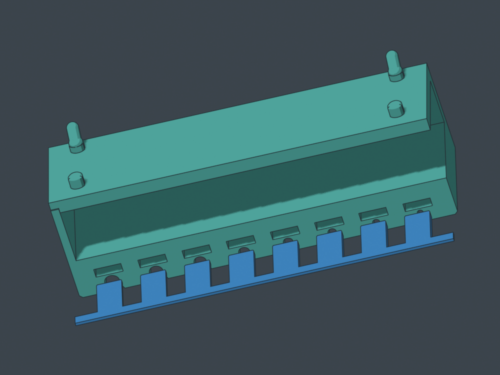
Load after printing. No pause, no permanent cap. The channels face down when mounted: the matching comb below (or loose spacers) plus removable tape keeps the magnets in place for the trial.
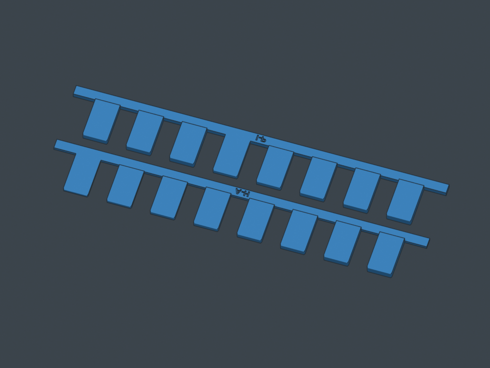
One strip holds all eight magnets.
New: matching A-H and I-P retaining combs. Both print flat. These replace the loose spacers in the v3 holders. No holder reprint needed.
- Comb-only print kit ZIP
- Both combs, flat — sliced P1S / PLA job
- Editable Orca project
- A-H comb STEP
- I-P comb STEP
- A-H print-flat STL
- I-P print-flat STL
One P1S / 0.4 / PLA plate: 9.47 g, about 30 minutes for both. The 16.8 mm fingers leave 0.2 mm nominal end play behind the magnets. Pull the rail to remove all spacers together, then tip out the magnets.
Load after printing. Tape the rail onto solid holder material, clear of the tool slots. Each labeled comb matches its own half; all fingers lie on one broad print face. CAD insertion, magnet clearance and tool withdrawal checked; sliced with no supports or pauses. Physical fit remains untested.
Rotate the flat combs
Original v3 holder kit
- Complete print kit ZIP
- Sliced P1S / PLA job — no pauses
- Editable Orca project
- Loading and recovery instructions
- Letter feedback sheet
P1S / 0.4 mm / PLA. Three plates: sixteen spacers (9.25 g / 31 minutes), A-H (103 g / 4 h 8 min), I-P (101 g / 4 h 5 min). Each strip is 150.4 mm wide.
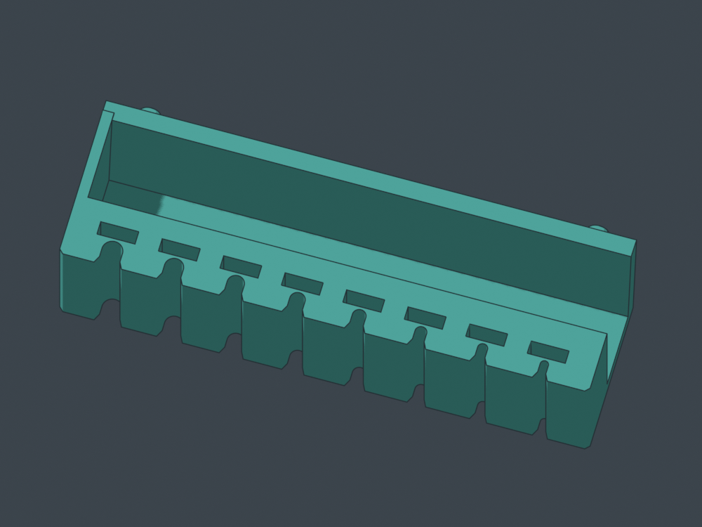
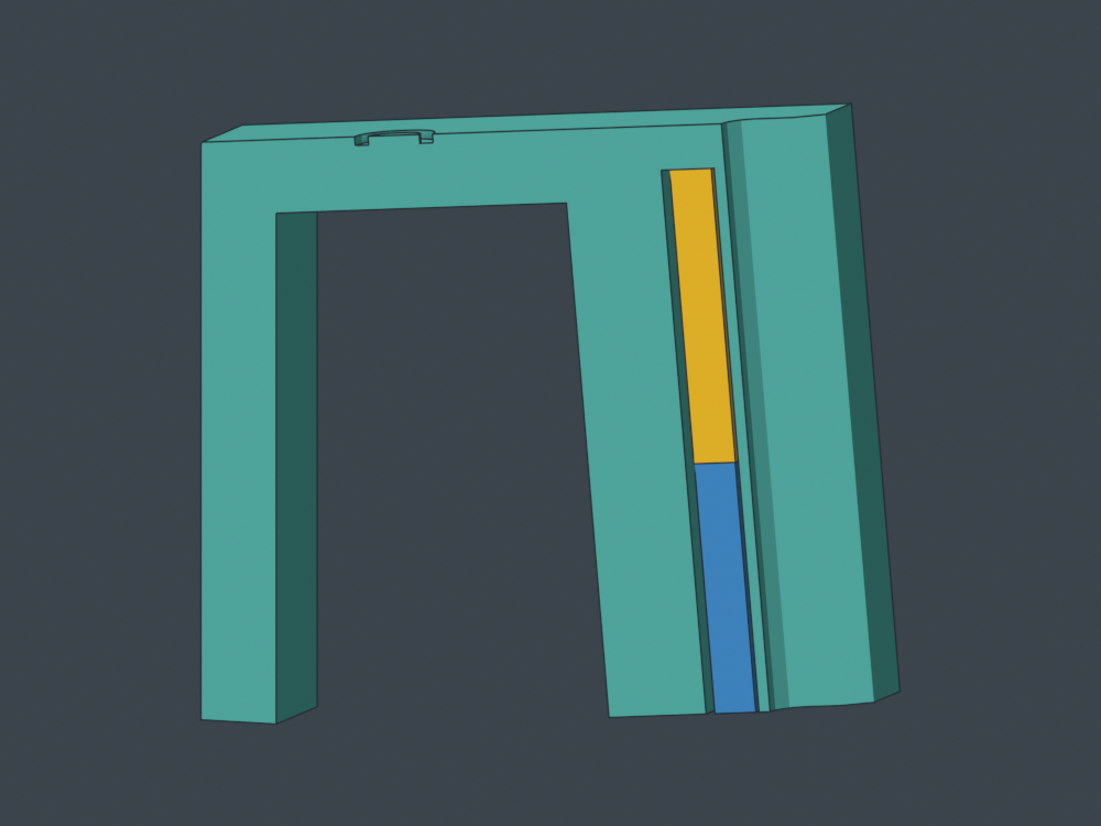
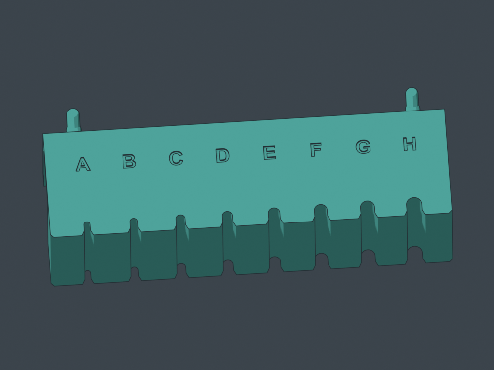
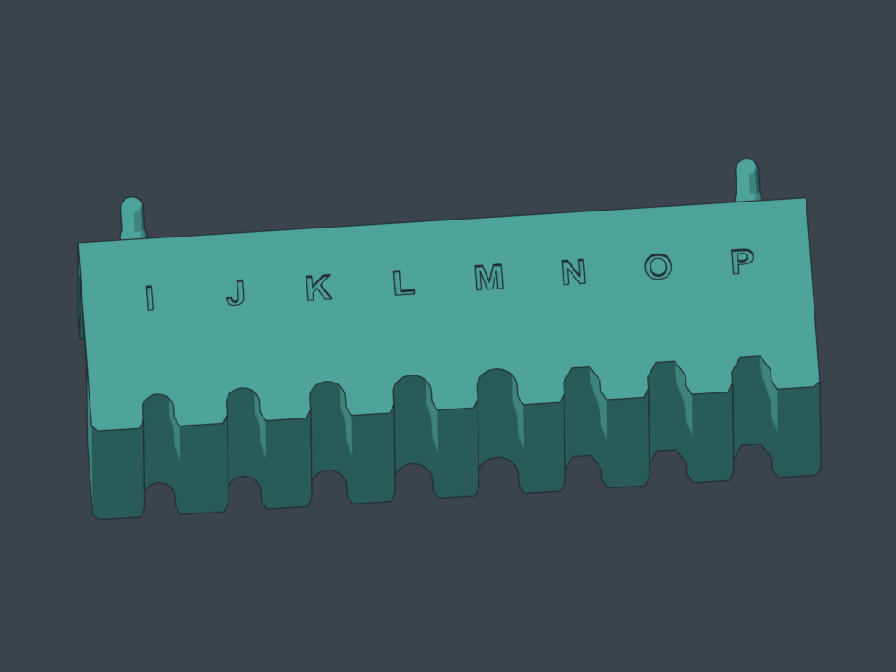
Load, test, recover
- Finish the print and let it cool. Hold the strip inverted with its channel mouths upward.
- Slide in a magnet, then a 17 mm loose spacer. Tape across the mouths and onto the solid back of the bar, clear of the tool seats.
- Mount and try one driver at a time. You can move a single magnet between letters.
- Remove the holder, support it over a tray, peel the tape and slide the spacer and magnet out.
Channels are 10.8 × 3.8 mm: 0.4 mm clearance per side around centered nominal magnets. The shaft-facing skin remains 0.8 mm. Magnets can move within the clearance; keep them against that wall for repeatable comparisons. Actual magnetic feel and sliding fit await your test.
Rotate the real models
STEP and STL files
- part-ms01-shaft-fit-sampler-20x10x3-recoverable__v3__A-H__installed__fit-e586ab4ff6.step
- part-ms01-shaft-fit-sampler-20x10x3-recoverable__v3__A-H__installed__fit-e586ab4ff6.stl
- part-ms01-shaft-fit-sampler-20x10x3-recoverable__v3__A-H__print-flat-top__fit-e586ab4ff6.step
- part-ms01-shaft-fit-sampler-20x10x3-recoverable__v3__A-H__print-flat-top__fit-e586ab4ff6.stl
- part-ms01-shaft-fit-sampler-20x10x3-recoverable__v3__I-P__installed__fit-e586ab4ff6.step
- part-ms01-shaft-fit-sampler-20x10x3-recoverable__v3__I-P__installed__fit-e586ab4ff6.stl
- part-ms01-shaft-fit-sampler-20x10x3-recoverable__v3__I-P__print-flat-top__fit-e586ab4ff6.step
- part-ms01-shaft-fit-sampler-20x10x3-recoverable__v3__I-P__print-flat-top__fit-e586ab4ff6.stl
- part-ms01-shaft-fit-sampler-20x10x3-recoverable__v3__loose-spacer-print-broad-face-quantity-16__fit-e586ab4ff6.step
- part-ms01-shaft-fit-sampler-20x10x3-recoverable__v3__loose-spacer-print-broad-face-quantity-16__fit-e586ab4ff6.stl
What has been checked
Valid solids and STEP round trips; changes confined to the magnet channels; clear straight magnet/spacer extraction; unchanged seats and pegs; native sliced job and settings reslice; no mesh repairs; bed bounds and startup clearance. All sixteen channels remain open through the final layer, with no magnet-loading pauses. Physical printing, sliding and retention remain untested.