R13 · UPDATE 14 · 8 MM LED · OCTOBER 27, 2026
P1S USB light riser
A slimmer four-piece frame with downward-facing LEDs, a rounded shade and lift-in white diffusers. Tapered puzzle joints join the frame; overlapping seams keep light from shining through the joints.
Update 14: corner block for the LED strip joint
The strip's soldered joint and cord now sit in a block that pushes up into the rear-right corner from below. A factory strip with its cord and plug lays into an open-top route; nothing is threaded or soldered. The block is held by friction on two crescent ends at 0.20 mm clearance per side.
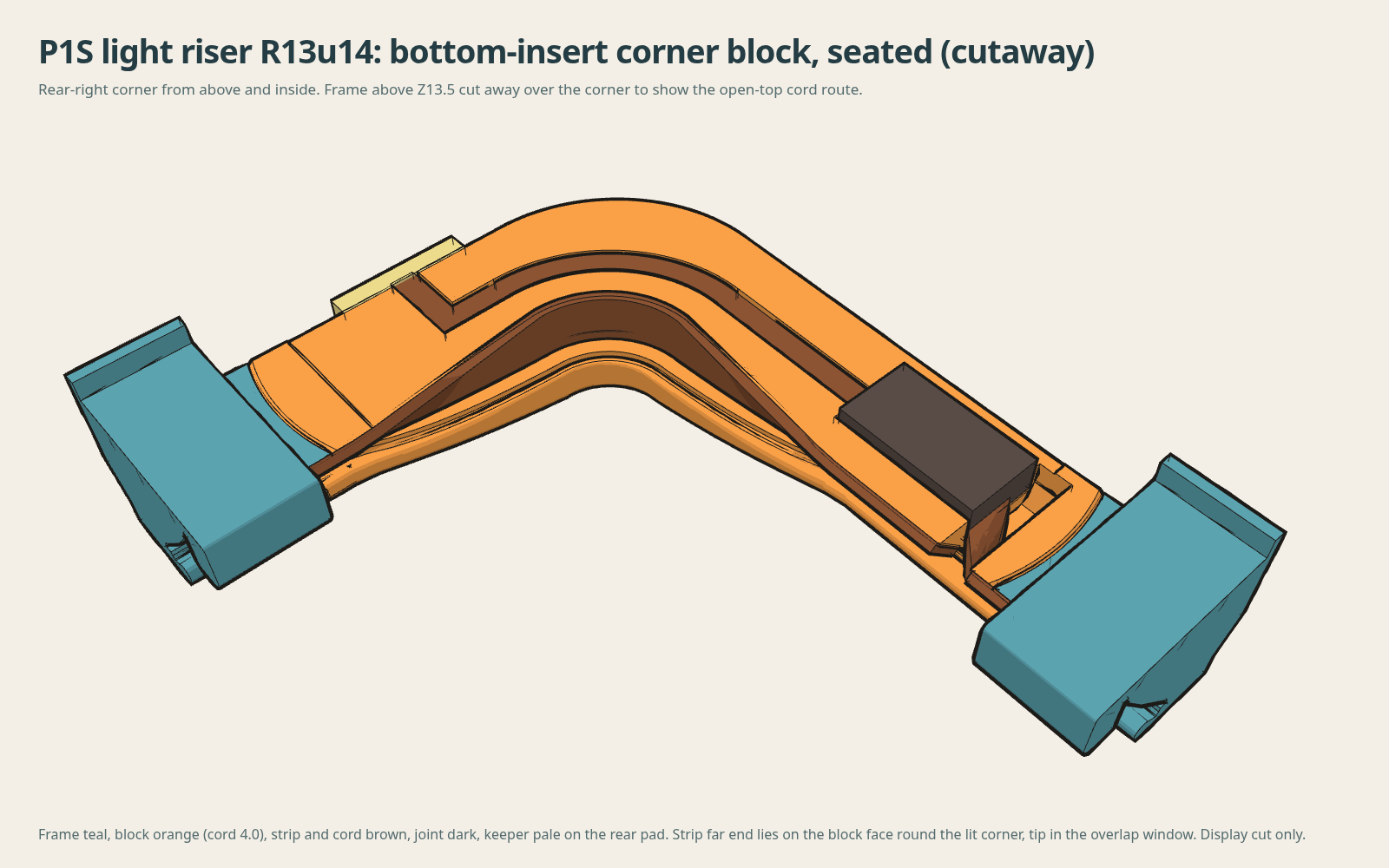
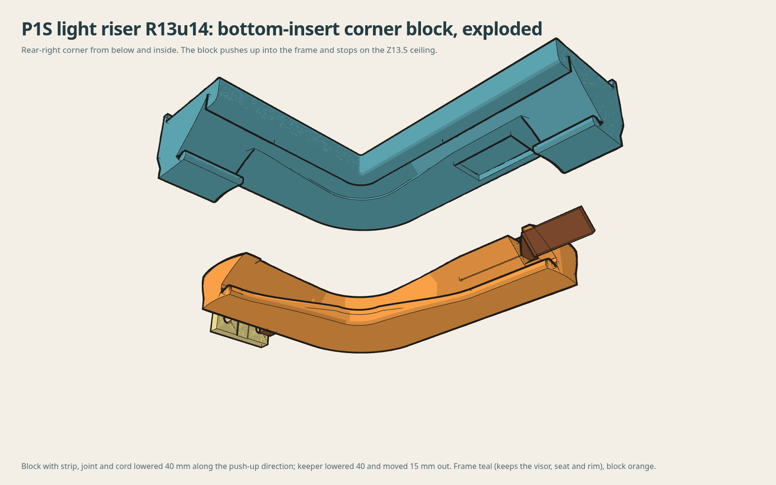
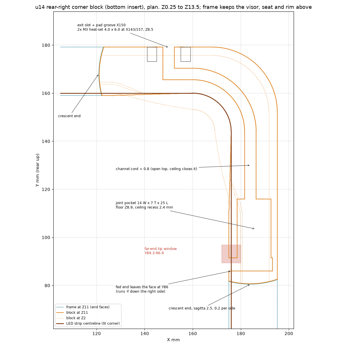
- Block: the whole corner body from the printer seat up to 13.5 mm, 1 mm below the visor underside. The frame keeps the visor, glass seat and rim.
- Joint pocket 14 × 7 × 25 mm; cord channel 0.8 mm wider than the cord. Blocks for 3, 4 and 5 mm cord, plus a blank.
- Strain relief: two M3 heat-set inserts and a screw-on cord keeper on the back face.
- Since update 10: thicker quarter seams (u11), a 3.4 mm glass rim and lid-handle pocket (u12). Overall height 26.9 mm. These quarters do not mate with update 10 quarters.
- The rear-right ceiling over the block spans 140 mm and needs support from the bed.
CAD checks pass: 64 of 64 assembly checks and all 21,125 sampled seam sightlines blocked. The corner block has not been printed; print the included socket coupon with the 4 mm block first. Three update 10 quarters have been printed in PETG. Checksums
The interactive views below show update 10.
Update 10 assembly and cutaways
Drag to orbit. Right-drag or two fingers to pan. Scroll or pinch to zoom. Double-click to reset. Full-size viewer · Image
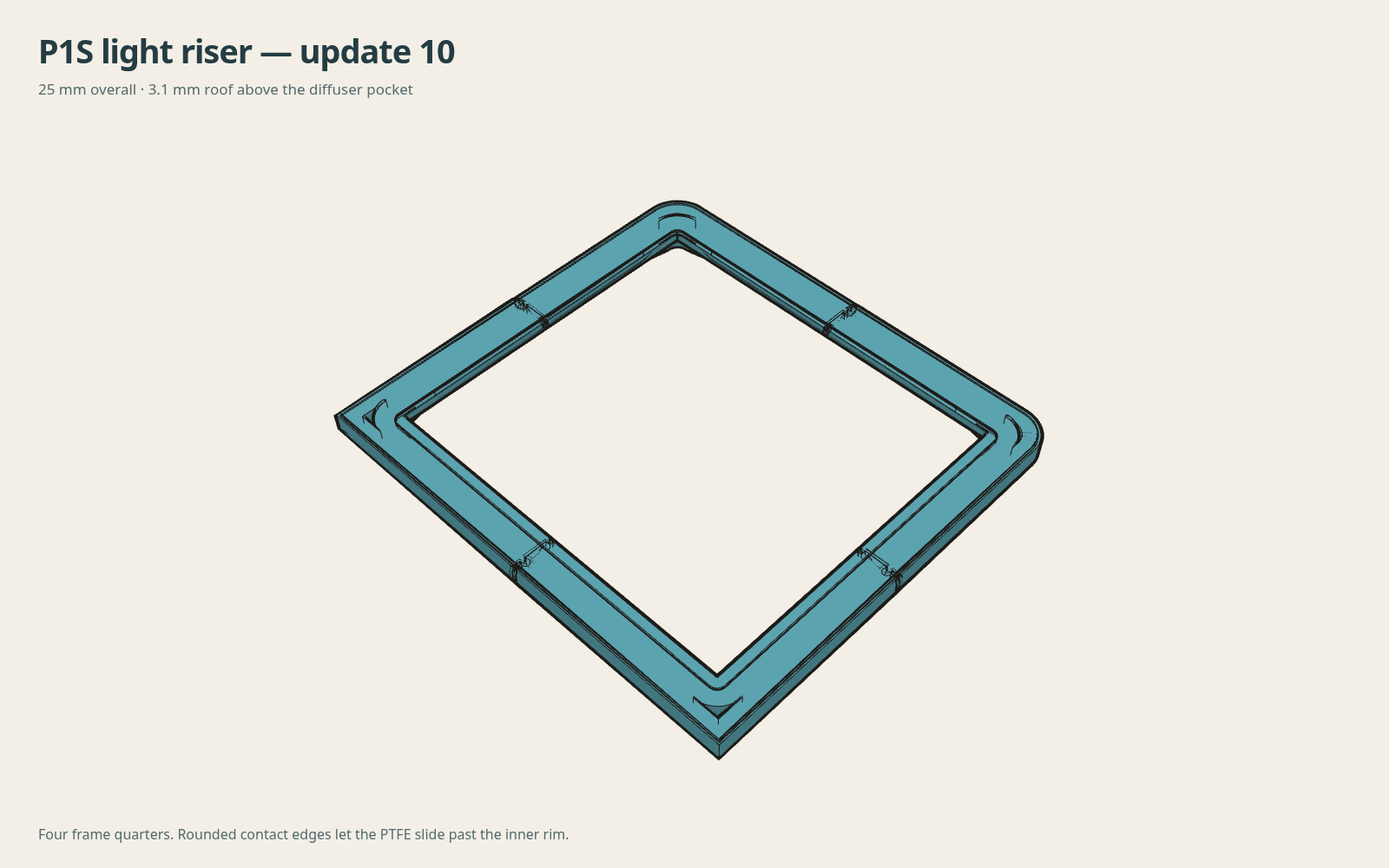
Download update 10
Four frame quarters, four diffusers, a cable plug and a joint-fit coupon. The assembly STEP shows the frame, diffusers and cable plug together.
This revision has passed CAD checks; a physical fitting trial and fresh slice are next. The 10 and 12 mm versions have checked sections, but complete kits are not ready.
A lower, simpler frame
Four quarters meet at tapered puzzle joints with overlapping seams. The joints are intended to hold without glue; the small coupon lets you check the fit first.
- 25 mm overall height; glass seat at 23.5 mm. Roof above the diffuser pocket: 3.1 mm.
- 390.4 × 358.4 mm outside; 387 × 355 mm glass pocket.
- 14.8 mm lower foot and 34.2 mm total cross-section width on straight runs.
- 1.7 mm glass-retaining wall, 1.5 mm high.
- 8 mm LED strip, aimed 45° down on straight runs and upright around the corners.
- Rear cable tunnel with a removable plug.
The exterior chamfer starts 0.2 mm above a provisional 3.5 mm printer lip; its actual height still needs measuring.
Lift-in diffusers
Lift the diffuser into the upper pocket, move the bottom over the rounded slot entrance, then lower it into the seat. The entrance has no flat shelf to catch the thin edge. Small CA dots at the hidden upper contact are optional.
The straight diffuser face lies at 30° above horizontal, flatter than the LED backing. It is 0.6 mm thick, with 1.6 mm of insertion lift. Assemble the frame before fitting the strip and diffusers.
Printing
The frame prints seat-down. PET-GF15 is the current material choice; PETG is an alternative. A three-piece PC support prototype fits beneath the visor, with tapered puzzle joints and low locating feet. Its glue-stick release surface still needs a coupon trial. Bed-starting edges use 30° chamfers from vertical (60° from the bed). The higher edges that the PTFE tube touches stay rounded.
Use your tuned machine, filament and process profiles. Try the matching PC tool and visor coupons first. Organic supports from the build plate only are an alternative. Check support contacts and printhead clearance in the sliced preview.
The new frame and thin diffusers still need a fresh slice and fitting trial. The download contains geometry, not a pre-sliced print job.
Light into the enclosure
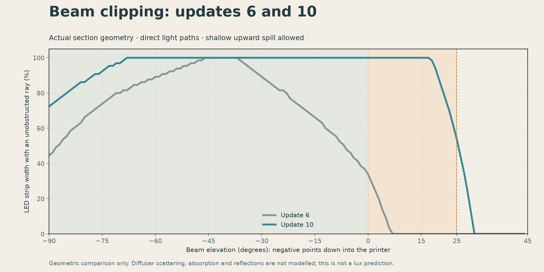
The shade hides the LEDs from steep overhead views while allowing shallow upward spill around 20–25°. Opening the lower edge gives more of the downward beam a clear path.
The section model passes about 69% of the assumed light output downward, compared with 56% in update 6. This is a geometric comparison, not measured brightness: diffuser scattering, absorption and reflections are not modelled.
Beam comparison
Geometry checks
64 assembly checks and 12 diffuser lift positions pass. The LED backing, glass pocket and cable plug clear their checked boundaries. All 21,125 sampled seam sightlines are blocked; all 1,300 sampled 45° downward rays clear the frame.
Physical joint fit, diffuser insertion and the fit on the printer remain to be checked. The full-printer lighting view uses a simplified printer mock and uncalibrated lighting. Detailed CAD results · Beam calculation