Reusable visor support
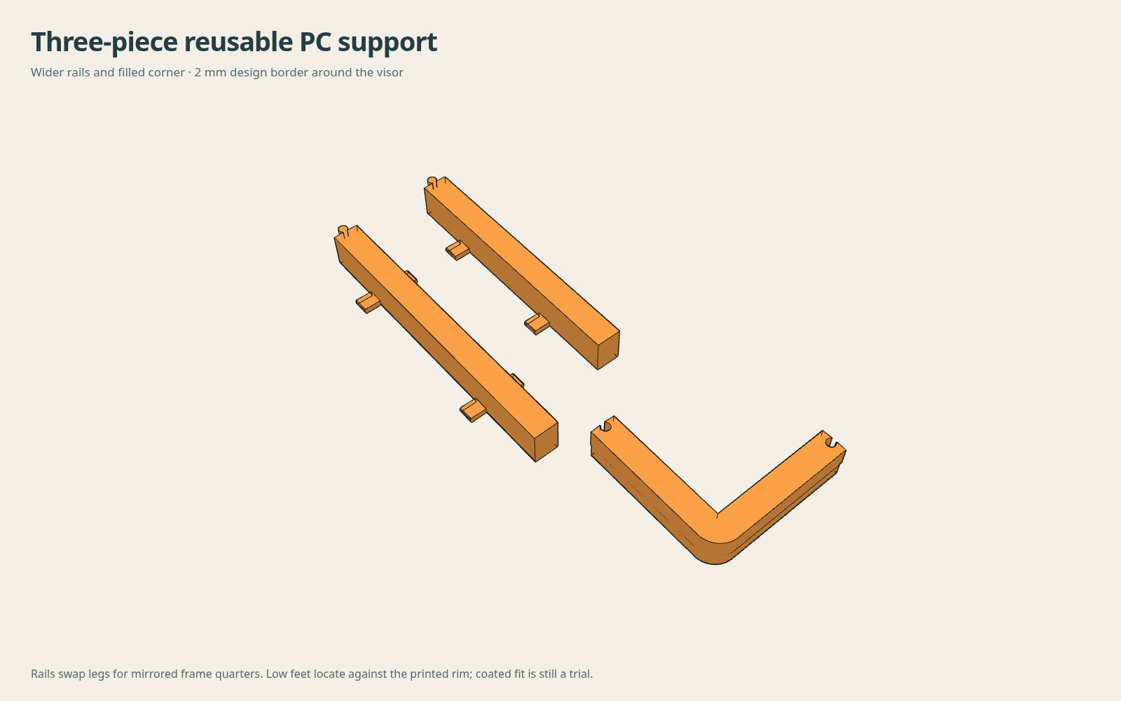
A PC corner and two straight rails join with tapered puzzle keys. Swap the rails between the legs to use the same set for all four frame quarters. Low feet locate the tool against the frame already on the bed. The wider rails and filled corner extend at least 1.5 mm past the complete visor footprint.
Support and contact surfaces
Drag to orbit. Right-drag or two fingers to pan. Scroll or pinch to zoom. Full-size viewer · Image
Download the prototype
The kit includes a small PET-GF15 visor coupon and matching PC support coupon for testing the glue-stick release surface before a full frame print.
Visor coverage checks · Clearance checks · Download hash · Attribution
Locate it, then slide it home
At the insertion pause, lower the assembled tool into the opening about 12 mm inward along each axis. Rest the feet on the bed, then slide outward until they register against the printed rim. Removal reverses that movement.
Lowering straight into the final position would catch the feet on the LED backing. The checked route enters farther inward first.
Height and release coating
The support follows the full visor footprint with a 2 mm design border. The checked minimum stays above 1.5 mm with ±0.2 mm placement play across all four quarters. The small sliding clearances at the puzzle joints remain.
The bare tool is 14.44 mm tall, 0.06 mm below the CAD visor. The feet have about 0.20 mm side clearance; puzzle keys have 0.10 mm radial clearance.
Use heavy glue stick on the top contact faces, let it dry, and check the coated height. The film can be thicker than the bare gap.
The final height and insertion pause need checking against the sliced layers and printhead travel. The geometry checks pass; coated release and reuse still need the coupon trial. No probing or re-zeroing is part of this method.