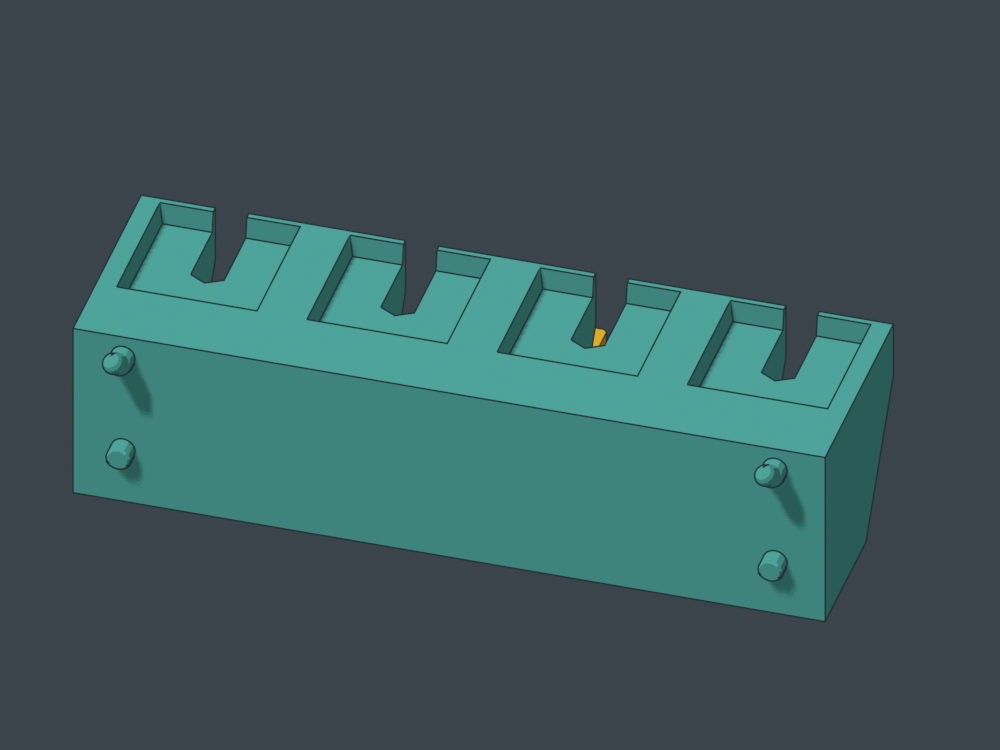
Magnetic screwdriver rack C v1

Four standard drivers · seven grid cells · 175.8 mm wide · current canonical tighter pegs.

Model review, not a ready-to-run print. Magnet size is provisional: four 10 × 10 × 3 mm block magnets, magnetized through the 3 mm thickness. Magnetic pull, plug grip and thermal suitability remain untested. A and B are preserved.

The intended motion

The flat seat carries the handle. A 120° V saddle locates the shaft below it; the magnet supplies gentle rearward preload. Lift approximately 6 mm to clear the shallow seat, then pull forward. Reverse that path to return. This geometric path is clear for the nominal 6.35 mm shaft / 30 mm flat-shouldered handle envelopes; actual shoulder shapes and magnetic release force still need a trial.

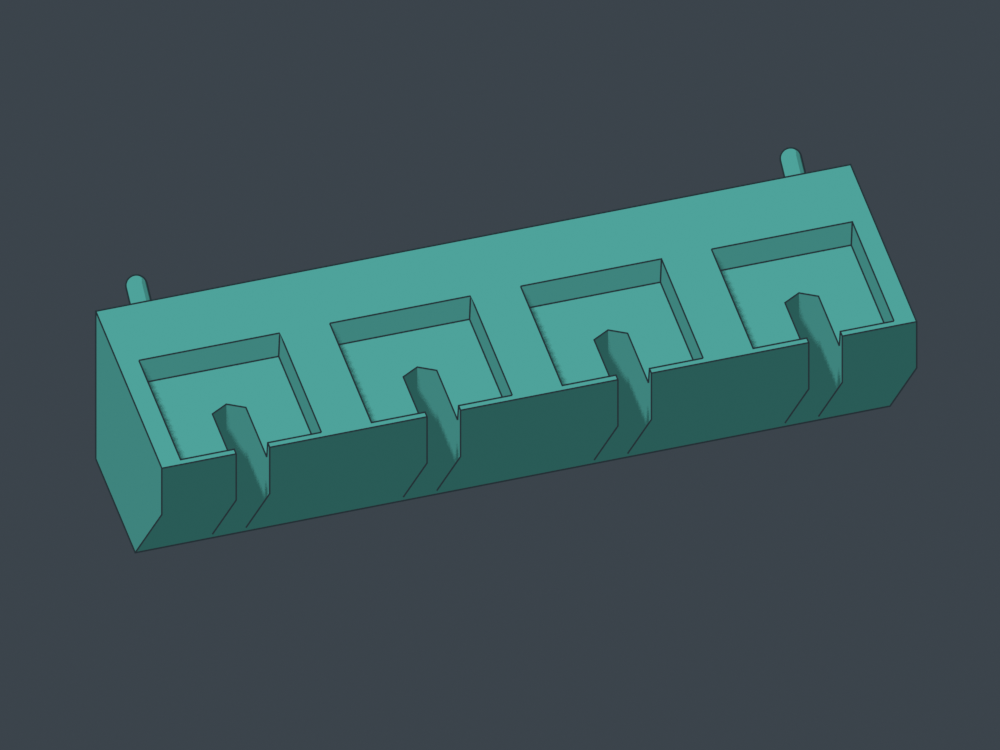
Flat shoulder seats and open V shaft saddles
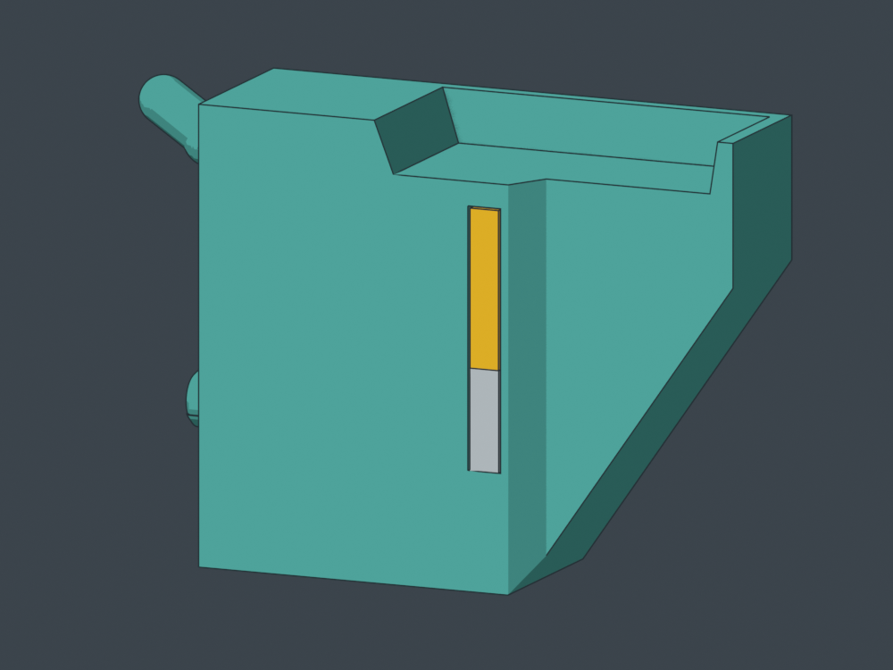
CAD half-section: silver magnet, yellow long plug; the teal cap closes above both
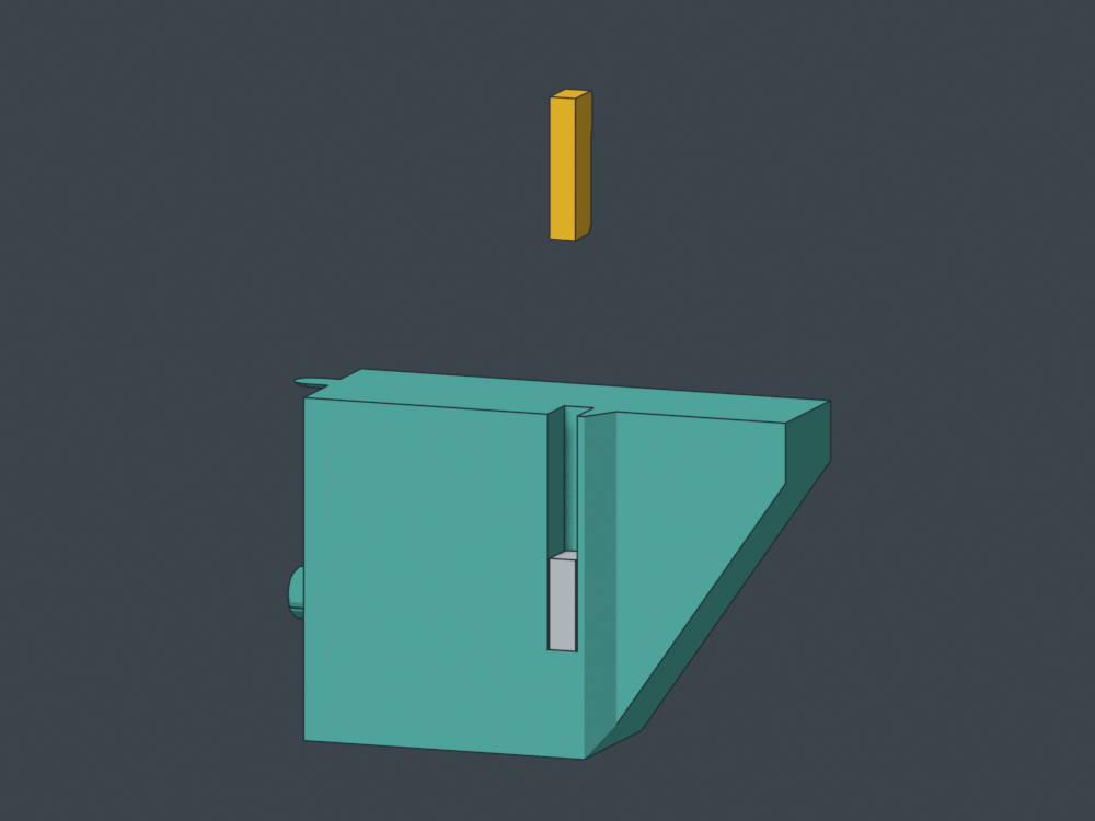
At the pause: magnet seated at the bottom, preprinted plug raised for illustration
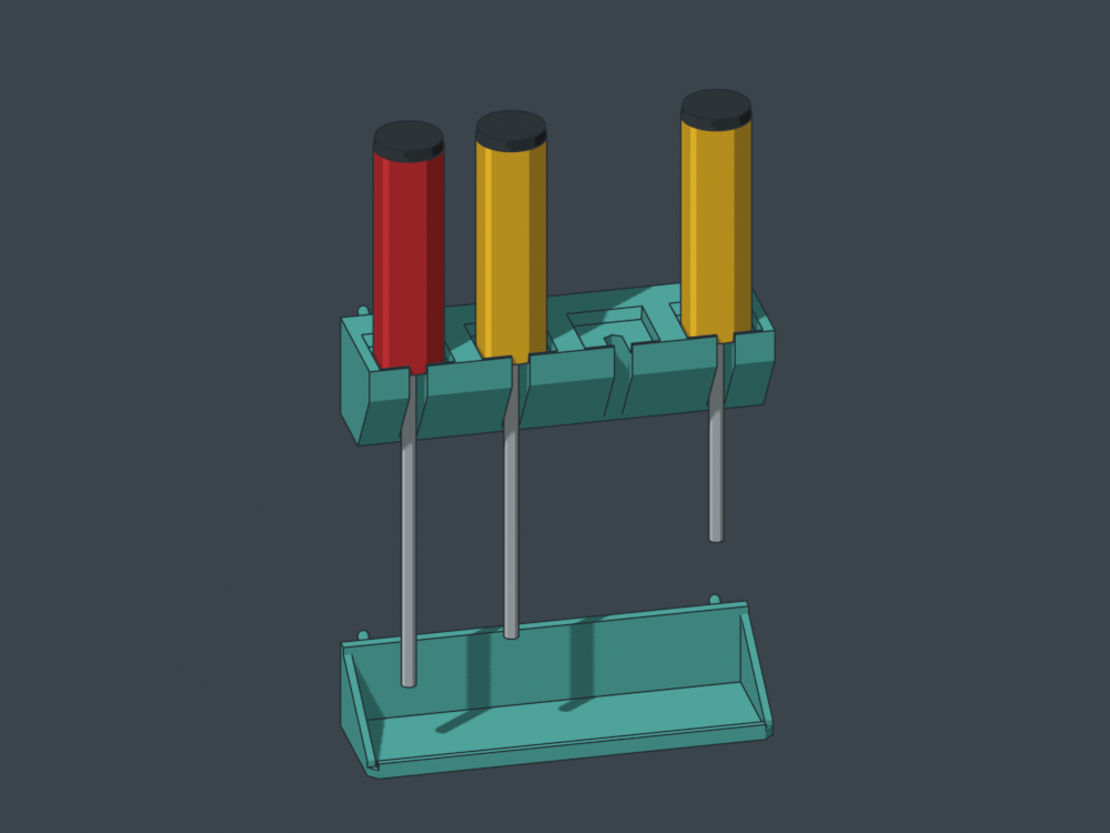
Three illustrative flat-shouldered drivers and one empty seat; separate tip floor retained
Broad base print pose; plug prints separately on its broad face, four copies

Pause and load

  1. Print four plugs first, lying on their supplied broad face. Check plug fit before committing to the rack. The 0.125 mm-per-side upper ribs are intentional interference, not a proven holding force.
  2. Print the rack upright on its broad base. All four rectangular loading pockets finish at the same height.
  3. Pause before the first closing layer, with the head parked away. The CAD opening is at 37.6 mm above the rack's print base. Only for uniform 0.20 mm layers including the first layer, this corresponds to after layer 188 / before layer 189. Verify that against the actual sliced toolpath; no pause G-code has been generated.
  4. Drop each magnet edge-first down its 10.4 × 3.4 mm loading pocket. Its square face faces the shaft. Push a plug down onto it. The plug's top is designed to sit 0.2 mm below the pause plane, with no material protruding into the next layer.
  5. The magnet top lies 15.8 mm below the closing plane. The long plug occupies 15.6 mm above it. Resume only with the inserts seated and retained; distance alone is not a guarantee against attraction to the toolhead. A 2.4 mm printed cap closes the chimney beneath the handle seat.

The V-apex skin is 0.8 mm; nominal shaft-to-magnet distance including cavity clearance and V geometry is approximately 1.49 mm. Magnet grade has not been selected. Test the chosen magnet and actual shafts before relying on this retention.

CAD downloads

Installed rack: STEP · STL

Rack in upright print orientation: STEP · STL

Plug — print four: STEP · STL

The separate floor protects the tool tips and is unchanged. Match its mounting height to actual tool lengths.

Reference tip floor: STEP · STL

Dimensions and geometric checks

What was checked

Valid single-solid STEP reimports, closed STL boundaries with preserved internal voids, clear magnet/plug loading paths except intended plug-rib interference, and nominal tool lift/forward motion. The rack is one solid with four closed internal cavities. P1S bounds checked. Rear peg supports, layer behavior, pause timing, magnetic forces and physical fit are not qualified.

Current fit authority: reference/peg-fit.scad, SHA e586ab4ff6173c76e10c960ca707da94b01c615a629480d4bceeae71c80e2438. The generator rereads it each time; downloaded CAD is a frozen snapshot.